Moving A/C devices from one leg to another

370Dancer

Well-Known Member
Oct 2, 2006
2,489
Suncoast of Florida
Boat Info
1998 370 Sundancer
Engines
380hp MAG MPI Gen VI with V drives
I am assuming that if I were to move, say one of the air conditioners from Leg 2 to Leg 1, that I am going to have to also identify the White Neutral, and probably ground, to move from the common Leg 2 bus to the Leg 1 bus as well?
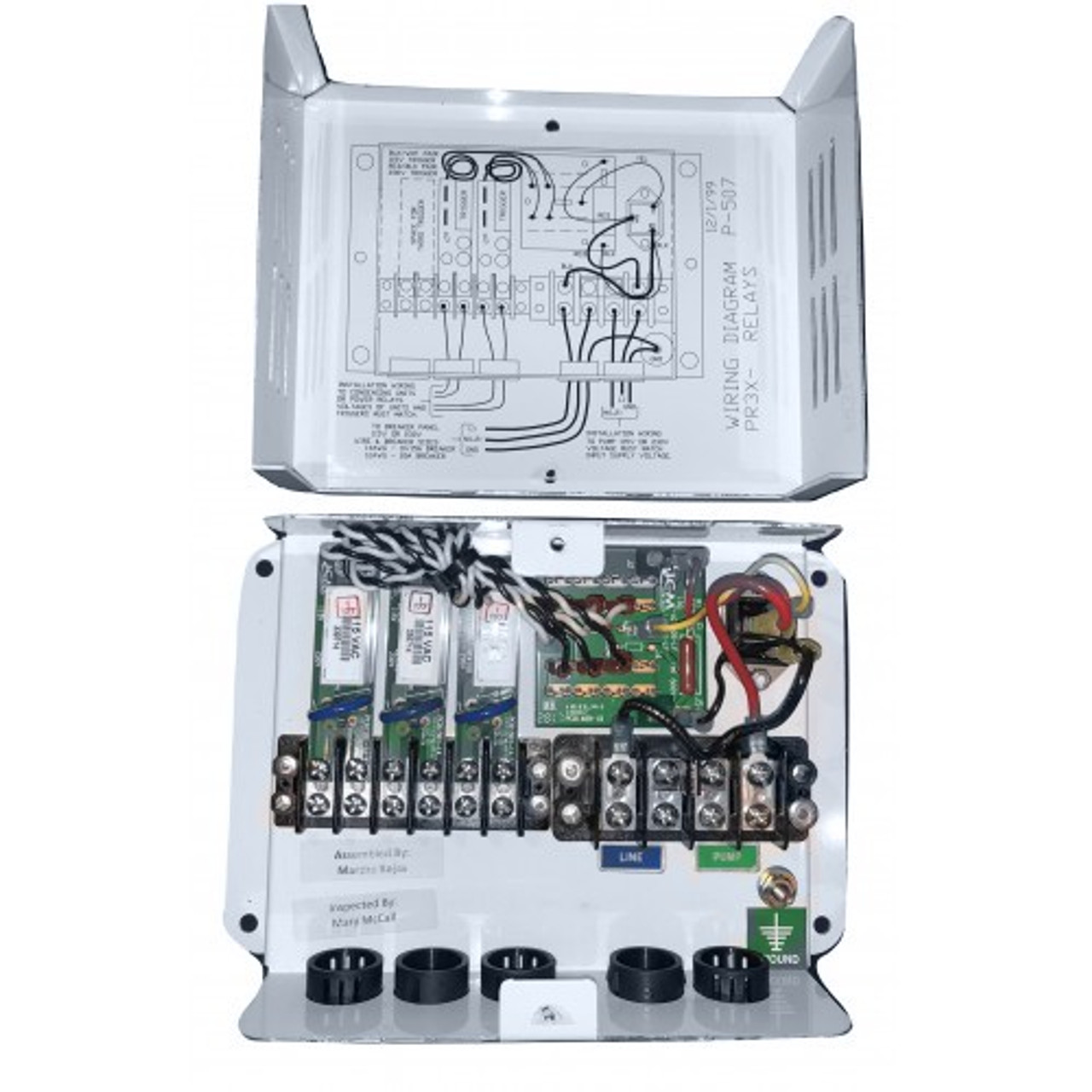
There is a "relay panel" that is fed power by the Leg 2 Aft AC breaker, which powers the common AC raw water pump if either AC has demand for cooling. That puts a wrinkle in this puzzle.
I've put larger ACs in than factory, and need to re-distribute the loads accordingly.
any experience doing this?
 

Attachments

  • Good 1998 370 DA Owners Manual Tab 12 salon AC wiring.pdf
    41.6 KB · Views: 59
crickets.................................. Did I finally stump the band?
I think I'm going to have to remove the relay box for the water pump from the loop to get this done. I think it's causing the common crossover from leg 1 to leg 2, which is tripping both legs.
 
So you're currently tripping both sides of your panel? Is this due to the overloading of those circuits or is it shorting somehow from that relay?

It's a bit hard to follow what's going on with your posts. We probably need pictures :)
 
Pictures... or a diagram/drawing.

Not sure I'm following the request right nor the problem, but if you move a hot then you have to move the neutral too or your're going to trip GFI's somewhere in the system.

The relay box shouldn't be a big problem, it should just activate when one of the ACs are on, even if they are on a different main panel.

And rather than change the wiring... did you think about a "soft-start" module for either or both of the AC units?
 
crickets.................................. Did I finally stump the band?
I think I'm going to have to remove the relay box for the water pump from the loop to get this done. I think it's causing the common crossover from leg 1 to leg 2, which is tripping both legs.
The Pump Relay box can be on either leg - it is completely isolated from the AC units.
To answer your question regarding the electrical power neutral legs - Yes they must be on the same supply as the Hot leg assuming the system is 120 volts. If your system is 240 volts then there is no Neutral. The only conductor that doesn't matter is the ground as they all tie into a common ground buss bar.
 
The ship's wiring is an attachment in the original post. There are no wiring diagrams for the appliance side, i.e. the A/Cs. I found out a long time ago that the circuit that energizes the relay box for the pump is powered off of the Aft A/C breaker. Yes 120. Tripping because of wiring, not load. finding the neutral that corresponds to a given A/C unit is proving to be a contortionist exercise over the stove. Not marked per se, but I am figuring which is which buss bar wise.
Can't work on it very long at a given time.
wanting to move it because I have replace a 9K and a 12K with a 11K and a 16K set of units. I am burning up shore power connectors if I try to run both. Just want to distribute the load so both can run in August down here when needed.
I'll do more tracing, and report back after the weekend.
So the pump is on the Aft A/C circuit breaker. And, you are up-sizing the load on that breaker with a larger BTU A/C unit?
Even though the system starts the pump before the compressor starts I'd move the pump to a new dedicated circuit breaker. Consider this - the Forward A/C unit is running and as a result has activated the pump; Now the larger Aft A/C starts with the pump already running and on that circuit. That is a lot of current for that circuit breaker you may be tripping that breaker before you know it....
That's how my air con units are wired. Each unit is on a dedicated circuit, plus the air con pump is on it's own circuit as well.
 
Wondering which breaker(s) are actually tripping? And when exactly are they tripping?

I don't think the on-board ones are GFI, so changes to the neutrals wouldn't affect them. It could cause some havoc in troubleshooting, but shouldn't trip the breaker(s). If it's the shore breaker(s) and they are GFI then it makes some sense.

I did see the wiring diagram, but it wasn't clear what modifications you were trying to do, or what part of that diagram was having problems.

And you should easily be able to run a 16K and 12K btu air conditioners on a single 30A circuit. A 9k and 12k would be even easier. That's done all the time (and it also includes the pump). But just don't use the microwave that's tied into the same side.
 
How much bigger of an AC did you install? I would think there is enough headroom on line 2 to go up a size. However as Tom points out you may get into trouble with the start up current. Moving the AC Pump/Relay to a separate breaker might help (Thats how it is on my 410).

Or you might solve that with a couple soft starts. You may be able to get away with one on your larger AC.

https://www.micro-air.com/products_easystart_364_softstarter_microair.cfm
 
Also, looks like leg 1 already has a lot of high demand appliances on it (water heater battery charger and the fridges). Moving an AC to that side, might cause problems there.
 
Okay....I'll weigh in..... A 12k is good for 11 amps running and the 16k is good for 15 amps running. Out of the box you are at 27 amps on one leg. The start spike would easily push you over 35 amps (should show on your amp meter) and depending on how long your shore cords are.......I can see why you are burning up cords.

As to moving one to the other leg.......it comes down to identifying the 12/3 (or 14/3) wire that feeds each appliance. Oftentimes you have to cut the zip ties that hold the appliance wire bundle to figure it out. All the appliance wire is zip tied together and other than wire size 12/3 versus 14/3 you have to mark each based on the black wire connecting to the breaker.

Once you know what that is .....it is a matter of moving the Outlets (15 amps) for example from the left side to the right side of the diagram and the smaller of the two ACs from the right side to the left side of the diagram. No problem identifying the black wire......you just have to follow it back to the jacket then follow the white wire out, mark the busses and shift the wires. Yes......I know it is a tight space over the stove. I also believe @ttmott is right that you do not need to move the green wire since it uses a common bus to both sides.

My only concern with the effort is that 16k unit. You may need to upsize the breaker on that to 20 amps instead of the 15 shown on the diagram.
 
WOW I'll have use the crickets cattle prod more often.....:)
Tracking every thought and suggestion. Yes I will likely move to soft starts, jeez, 400 each?!. I'm in conversation with Marinaire to see if they have any soft start circuitry built in, but it doesn't look like it.
Getting to the end of the jacket where the 12/3 is coming out is the chore. They are DEEP in the loom, and I'm sure when the electrician was wiring it, he was standing in the stove/fridge cavity. I'm sitting on stove knobs, reaching in as far as I can.
My fridge is a new Isotherm, which already has some soft start circuitry built in. I hardly ever run the water heater, as The engine does it for me, and, well it's SW Florida. Don't think we've used the stove more than once in 25 years. Microwave is much more likely, and I'm smart enough to turn off that A/C before running it. A/C converter is on full time, but the Pro Mariner is managing that pretty well. I can barely see any draw on the amp meter.
The A/Cs and the raw pumps are all on their own circuits on the Portofino, so I am aware, and do have a spare "Accy" blank in the panel I could use for the raw pump.
Even beeping the wires out is not really working well. I'll have to physically find them, and then confirm with a continuity check on each wire, when totally isolated from the boat. This would be a good time to cuss the fool that made flat blade screws for the buss bars. This would have been a 30 minute job if the buss bars and wires were properly labeled, but alas, they were not. This isn't my first rodeo with A/Cs or panel wiring. Roger on upping the breakers to 20A at the panel if needed. The tripping is happening at the power stand on the dock where they are both GFI breakers. The only real monkey wrench is the pump demand relay box. Hot and neutral go to both A/Cs, so if I separate the legs on the units, I may still have neutral crossover at the A/C control box. Too bad it's not a big boat, where you just assign circuits to legs to even the load dynamically.
And to clear up, the Fwd A/C is 16K (head, fwd cabin, and fwd Salon), and the Aft A/C is 11K, (Aft Salon, mid cabin, and blows at the galley 16K is running all day and night with the pump circuit on Leg 2 right now with no heat on the power cord. I'm moving the 11K up to Leg 1 to fade the draw on leg 2. I'll tackle some more this rainy weekend. And, of course I am labeling everything as I go, for the next guy. Thanks for the inputs.
 
That's how my air con units are wired. Each unit is on a dedicated circuit, plus the air con pump is on it's own circuit as well.

Same for me, three breakers, one for each unit exclusively and one for the pump exclusively.
 
... My only concern with the effort is that 16k unit. You may need to upsize the breaker on that to 20 amps instead of the 15 shown on the diagram.

Yep, my 16K in on a 20A breaker. And it is needed to your point, for the startup current.
 
Hot and neutral go to both A/Cs, so if I separate the legs on the units, I may still have neutral crossover at the A/C control box. .
The wiring from the A/C unit's control box to the pump relay box only activates a relay in that box (it is the relay coil) and does not power the pump unless someone did some hocus pocus. Those relays are either 120V or 240V. The pump itself is powered completely separately.
 
The wiring from the A/C unit's control box to the pump relay box only activates a relay in that box (it is the relay coil) and does not power the pump unless someone did some hocus pocus. Those relays are either 120V or 240V. The pump itself is powered completely separately.

Isn't the relay box so that more then one AC unit can turn the pump on/off? Doesn't that relay control the pump? If not why it is there? That relay on mine, from the factory, controls the pump.
 
Isn't the relay box so that more then one AC unit can turn the pump on/off? Doesn't that relay control the pump? If not why it is there? That relay on mine, from the factory, controls the pump.
The relay box is so more than one A/C system can use a common pump. Each A/C system has a trigger relay inside of that box. The A/C system only connects to the coil in the relay. The power for the pump is separate and is switched through the relay contacts. The pump is powered through a Triac that is activated by the trigger relays. This photo shows trigger relays that are replaceable for three A/C systems. The trigger relays can fail over time so I carry a spare on the boat.
ddd__39778.1548859660.jpg

Yes exactly, there is a separate breaker for the pump that powers the triac. I guess I missed your meaning, I read that the relay doesn't control the pump. My bad.
 
Agreeo on all that. Prior to looking at the schematic for the pump relay (I'm still using the old Cruisair one that came with the boat), I was concerned that there might be some neutral sharing in the relay box. Looks like they are isolated enough that it won't matter. I am inclined to put the pump power on the Accy blank in the panel to overcome the issue of only running the fwd air, with the aft air breaker off = no seawater. Most people probably don't control their A/C on off by the panel breaker, but I do. It's at eye level and easy to read. The Marinaire thermostats........not so much for these old eyes.
AC Trigger board for pump.PNG
 

Forum statistics

Threads
113,186
Messages
1,428,171
Members
61,097
Latest member
Mdeluca407
Back
Top