Westerbeke 8kw BTD No AC

kvduff

Well-Known Member
Jun 22, 2011
715
Long Island N.Y.
Boat Info
1998 450 Sundancer
Engines
Caterpillar 3126 -420hp
Generator is original to my 98 450 Sundancer. Yesterday was running the generator , powering the salon air and forward stateroom air along with the refrigerator. When I arrived at my destination I went in to the cabin and didn’t feel much air conditioning. Generator was running but less then 10 bolts was indicated on the meter in the panel. Lefl it alone for the night and spent some time today running through the diagnostics in the service manual

page 3 indicated for low or no voltage to run the sequence of tests listed in the pic below

1st step was to test main stator windings which was explained on page 10. Posted below.
When I performed the test on c1 and c2 I couldn’t get any resistance reading on the meter.
With out any reading of resistance is that a clear indicator of the stator windings being toasted?
I haven’t done any further testing described in the sequence on page 3. I did however, start the generator and at the circuit breaker I was reading 2 volts on each leg.
2 questions.
1 is my finding of no resistance indicative of failed back end.
2. Should I continue the further test as outlined on page 3 even though the first step isn’t giving the .6 ohms as indicated in the manual.
87E538CA-9C54-4ED7-AF3B-7ED88E4F2464.jpeg
5BBD08ED-27D9-44F9-B6CD-3CBF784A1578.png
 
Short season and heading on vacation for ten days. Need to get this sorted out sooner than later. After initial diagnostics, I
removed the back end today. Need to see shipping rates from ny to broward armature. There are a few people around the ny area but broward really seems like the experts on these westerbekes.
 

Attachments

  • 82D5DA07-D31A-4B75-B71D-25BD70587006.jpeg
    82D5DA07-D31A-4B75-B71D-25BD70587006.jpeg
    143.7 KB · Views: 156
  • 47F8D1AD-B94F-4744-9E0B-A1BE3EE5B972.jpeg
    47F8D1AD-B94F-4744-9E0B-A1BE3EE5B972.jpeg
    125.6 KB · Views: 162
Unusual failure - corrosion? I don't see any in the pics. Did you check the stator again after removal making sure it wasn't the terminal connection?
Being you are in that deep probably smart to replace the diodes, thermistor, and voltage regulator...
Broward seems to be the go to for Westerbeke rebuilds. Have you called them?
 
To be honest after following the steps in the service manual, I just want it fixed.
Spoke with Broward briefly. The work to rebuild isn’t too bad. Low 3k
Just concerned about shipping costs. The guy here in nyc wants 4K. I could deliver it but, broward seems like the experts. Making a few calls today, then driving or Crating for shipment.
 
When I spoke with them the shipping was like $170 each way. They use R&L shippers (trucking)

Get a pallet and shipping straps, and plastic cover or box.
 
Shipping is freaky expensive these days.....
We have been using Yellow Freight. Local crating company then drop off at receiving.
 
427 each way puts them at a cost around 4K same as New York company who I can drop off and pick up from. Ny company does a lot of work in The marine industry. Only difference may be time. On the fence with direction to go!
 
Cost (and everything else...quality etc) being about equal, local guy might be preferable just in the event something just isn’t right.
 
Palleted, banded, and crated. Waiting for the generator to make its first trip back to Florida since it’s birth! Broward was much easier to communicate with than the local company and felt that Browards reputation was hard to ignore. The waiting begins.
 
Palleted, banded, and crated. Waiting for the generator to make its first trip back to Florida since it’s birth! Broward was much easier to communicate with than the local company and felt that Browards reputation was hard to ignore. The waiting begins.
What was Browards backlog? Can they get right on it?
Boating season, especially in NY is burning down.....
 
Well my back end has reached the guys at Broward, spoke with nice guy there today. Said it would be torn down over the weekend and rebuilt and ready to ship by next Wednesday. Fingers crossed and hoping for a quick turn around! Will post back about experience. So far so good!
 
Well my back end has reached the guys at Broward, spoke with nice guy there today. Said it would be torn down over the weekend and rebuilt and ready to ship by next Wednesday. Fingers crossed and hoping for a quick turn around! Will post back about experience. So far so good!

Following as we have the same boat & gen...
 
Hey guys it was a total of 24 days turnaround from the day my generator died till I got it back installed in the boat.

Few issues going forward and I’m completely confused
When the genny shit the bed, I was only producing 2 volts at each leg of black wires leaving the generator. I am now producing 120volts at each leg.
However I am confused because I am not making the necessary 240 volts to power the a/c and other 240v components. All the 120volt components are operating correctly and showing an amperage draw.

The voltmeter in the electrical panel isn’t registering any power. But like I said the outlets and microwave and the other 120 components are working.

I would figure that the the two 120 volt legs would connect somewhere to produce the necessary 240. But I am not sure where. Looking at the sea ray wiring diagram it looks like the jumper that comes from the second switch of the generator circuit breaker feeds power along an 8awg black to those 240 components. But I am only getting 120volts

Looking for a answers.
Should each leg coming out of the generator have 120volts?

is it the circuit breaker that joins the two legs to produce the 240?

Keep in mind I didn’t mess with anything other than removing the back end


Also the volt meter isn’t showing anything but when I meter it it’s showing 120 on both posts

I attached a marked up diagram to help understand. Any help is appreciated.
 

Attachments

  • C69CCA5F-F9EE-4A25-B274-901B99F14A5A.jpeg
    C69CCA5F-F9EE-4A25-B274-901B99F14A5A.jpeg
    92.3 KB · Views: 102
Last edited:
You should read 120 volts to ground for each of the L1 and L2 legs which it appears you are.
The issue is those two 120 volt legs are In Phase and should be 180 degrees Out of Phase.
You need to call Broward back and talk to them; I hope it is only a termination issue.
The white wire is bonded to the generator's chassis as well as the green wire.
Thanks for the response, I’m not exactly sure what it means that they are out of phase?
Broward had told me prior to shipping it back that they tested it… could they have tested to see 120v on each leg and not known that it was out of phase?
 
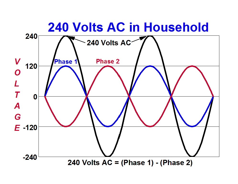
Take a look at this picture. Both of your AC lines are right now following Phase 1 so there will never be a differential voltage between the two lines (it will always read zero). There will be differential between the two lines and neutral/ground (shown as "0-" below) at 120 volts.
It should be set up so line 1 (phase 1) and line 2 (phase 2) are shifted apart 180 degrees like shown so the differential between the two opposing peaks (lines) is 240 volts yet still each line remains at 120 volts to neutral (the 0 on the graph). That is how it's done....
large.57581ad8d9a5d_240VACinResidentialPowerSupplies.png.f176ab25d2092125b3d05d648597b1f8.png
 
Last edited:
Take a look at this picture. Both of your AC lines are following Phase 1 so there will never be a differential voltage between the two phases. There will be differential between the two lines and neutral/ground (shown as "0-" below) at 120 volts.
It should be set up so Phase 1 and Phase 2 are shifted 180 degrees like shown so the differential between the two opposing peaks is 240 volts. That is how it's done....
large.57581ad8d9a5d_240VACinResidentialPowerSupplies.png.f176ab25d2092125b3d05d648597b1f8.png
Jesus Christ. I hope this is isn’t going to require another shipment. I appreciate your insight. When u mentioned a termination issue, could you explain that a little bit more? I had pictures and taped the wires, I know they all went back where they were originally.
 
Jesus Christ. I hope this is isn’t going to require another shipment. I appreciate your insight. When u mentioned a termination issue, could you explain that a little bit more? I had pictures and taped the wires, I know they all went back where they were originally.
It's probably simple - take a look at the winding terminations compared to this; you need to be configured as shown on the right diag. -
upload_2021-7-25_18-25-50.png
 

Forum statistics

Threads
113,241
Messages
1,429,127
Members
61,123
Latest member
Tim Duncan
Back
Top