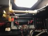
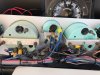
Is your Glendinning engine Synchronizer set up like this? Those two gray modules hanging off the sides are the DC Pulse tachometer drives. They are wired to the Synchronizer Gauge module behind the dash then from there to the tachometers and Sync gauges.

Navigation
Install the app
How to install the app on iOS
Follow along with the video below to see how to install our site as a web app on your home screen.

Note: This feature currently requires accessing the site using the built-in Safari browser.
More options
You are using an out of date browser. It may not display this or other websites correctly.
You should upgrade or use an alternative browser.
You should upgrade or use an alternative browser.
Synchronizer gauge stopped working
- Thread starter AllanS
- Start date

- Jun 5, 2016
- 5,592
- Boat Info
- 410 Sundancer
2001
12" Axiom and 9" Axiom+ MFD
- Engines
- Cat 3126 V-Drives
Dave, those Aetna tachs look tempting, but I think I need to first convince myself that the tach signals are of good quality before I spend good $ on new tach gauges.
Yes you’ll need to ensure your getting a good signal. If you have a good DMM, there should be frequency or maybe Hz setting that if you connect the leads while the engine is running, you should be able to see a pulse train. Start at the tach between signal and ground.
I am a big proponent of the Aetnas because with these old mechanical diesels keeping track of your WOT and running in the right rpm range is critical to engine life/longevity, especially as parts become more scarce/expensive.
Skybolt
Well-Known Member
- Nov 11, 2014
- 6,469
- Boat Info
- Reel Nauti
460 EC
- Engines
- Detroit 6v92TA
(Low profile's)
Alison Gears
Westerbeke
12.5kw Genset
Thanks for all your follow up research on the 3208, Dave, and both of your thoughts what might be what system I have. Looks like I need to take a closer look at the mechanical cables that are attached to the front of my engines, with pics, and see if there is any evidence of a sender that is converting the rotational movement into an electrical tach signal. My recollection of looking at where the cable attaches to the engine is it was just a simple connector, no sender with wires. I’ll look closer at the cable ends that connect to the Glendinning unit next. I know my tach gauges are electrically driven, so there have to be electrical sensors somewhere on the engines, which from what you guys report, are most likely from the mechanical cables at the front of the engine, possibly on the Glendinning unit, or magnetic senders near the flywheel. If I can find the tach senders, then I should be able to trace these to a synch module, correct? Interesting that the dash illustration that Dave provided shows the synch module E37 at the same location as the synch gauge.
Dave, those Aetna tachs look tempting, but I think I need to first convince myself that the tach signals are of good quality before I spend good $ on new tach gauges.
@ttmott posted a picture of what I was saying, your electronic tach senders are most likely on the Glendinning sync module. If you switch to the Aetna tach's (LCD version I posted) you should also replace the sending units as well. An expensive proposition but worth the investment. I would also ditch the electronic sync gauge and module.
EDIT: One thing about those type of sender, they are basically AC generators and have a very large signal. Upwards of ~70 volts, there really isn't a pulse train, it's more like looking at an AC wall outlet.
This post has an oscilloscope image of the raw signal.
http://clubsearay.com/index.php?thr...-analog-to-digital.101609/page-2#post-1190562
AllanS
Active Member
- Oct 30, 2020
- 180
- Boat Info
- 1989 440 Aft Cabin
- Engines
- Twin Caterpiller 3208 (375 HP)
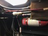
Thanks, guys!!! I’m going to the boat today and will take a good look. Just from recollection, ttmott, my Glendinning looks like that, but not with the gray modules. I’ll confirm today by looking for those gray modules on both the engine side and Glendinning sides of the tach cable.
AllanS
Active Member
- Oct 30, 2020
- 180
- Boat Info
- 1989 440 Aft Cabin
- Engines
- Twin Caterpiller 3208 (375 HP)
AllanS
Active Member
- Oct 30, 2020
- 180
- Boat Info
- 1989 440 Aft Cabin
- Engines
- Twin Caterpiller 3208 (375 HP)
So, given that my Teleflex tach gauges (yes, confirmed that today too) do a reasonable good job reporting rpm, can I assume the tach sending units are fine, as is the tach sync module (which I still cannot find)?
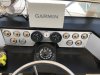
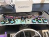
Attached are pictures of the helm gauges from and back. It appears that the tach gauges (port and starboard) receive a grey wire from the wiring harness, and then there are short, grey "jumper wires" from each tach to the tach sync gauge. Since the tach are working, does this mean the tach sync gauge is not operating?
Attached are pictures of the helm gauges from and back. It appears that the tach gauges (port and starboard) receive a grey wire from the wiring harness, and then there are short, grey "jumper wires" from each tach to the tach sync gauge. Since the tach are working, does this mean the tach sync gauge is not operating?
Attachments
AllanS
Active Member
- Oct 30, 2020
- 180
- Boat Info
- 1989 440 Aft Cabin
- Engines
- Twin Caterpiller 3208 (375 HP)
Regarding the inoperable starboard hour-meter, I confirmed that both the port and starboard hour-meters were getting 12.6 and 12.9V, respectively, with the engines idling. But again, only the port hour-meter clock advanced. I applied 12.8V directly to the starboard hour-meter from a known voltage source, and it did not advance the clock. Broken hour-meter? Maybe I should swap the meters and retest, just to complete the testing?
Skybolt
Well-Known Member
- Nov 11, 2014
- 6,469
- Boat Info
- Reel Nauti
460 EC
- Engines
- Detroit 6v92TA
(Low profile's)
Alison Gears
Westerbeke
12.5kw Genset
So now your saying the tachs that mostly work are now fine and the sync gauge still doesn't work, but you want that fixed even though your tach's are not stable throughout the operating range?
Your sync seems to be standalone if the tach signal is directly from your tach to the sync. Not familiar with that type and is most likely a change by the PO.
https://www.greatlakesskipper.com/boat-gauges-and-electronics?cat=5249
Your hour meters are simply defective. Just replace them, take photos of the originals in place and keep them for re-sale documentation.
AllanS
Active Member
- Oct 30, 2020
- 180
- Boat Info
- 1989 440 Aft Cabin
- Engines
- Twin Caterpiller 3208 (375 HP)
I started by asking why a tach sync gauge might not work, and have learned a lot about "tachometry" from you guys. Thank you!
What I've learned and observed:
1. That the electrical tach signal originates from the tach senders attached to the Glendinning unit.
2. I can trace the black and white wires from the tach senders within the engine room as they join the other helm instrument wires in a plastic conduit headed toward the helm.
3. I have NOT found a sync module ("hockey puck") as yet either in the engine room nor behind the helm instrument cluster, but I will look under the helm next, presumably that unit receives the input from the tach senders.
4. My Glendinning unit works fine, but since that's a mechanical tach unit, it has no bearing on the electrical tach signals going to the helm, other than the tach sensors which are turned by the tach cable, which appear to be working.
5. My sync gauge's needle points straight up (no response to engine rpm). Either it is dead or not receiving valid tach signals.
6. My Teleflex tach gauges do work, but can be erratic, and seem to "settle down" to consistent and believable rpm readings after a half-hour of operation.
What I think I need to do:
1. Find the sync module to verify wire integrity and how it connects with the tach gauges and tach sync gauge.
2. Based on what I find with the tach sync module (replace it and/or fix wiring), I'll retry the current tach and tach sync gauges.
3. I think you've convinced me that replacing the Teleflex gauges with Aetna gauges are the way to go. I do NOT know if I need to change the tach senders and/or tach module if I install Aetna tach gauges. Please confirm YES or NO.
The Sync modules that operate the sync gauges that we are referencing are definitely on later model boats (mid 90's to around 2003). I'm not sure any one of us really know how your sync gauge works - we are taking best guess. What we do know is your helm is getting the pulse signals from the two RPM senders (the tachometers are responding).
What you can do is put a good DVM on the signal wires (port and starboard) and measure if something of a frequency can be detected and that frequency changes with engine RPM. If there is, in fact, a varying signal then you pretty much have isolated to a failed gauge.
If there is a Sync Module you will get varying voltages at the sync gauge rather than frequency. Again that can be measured with a good DVM.
- Jun 5, 2016
- 5,592
- Boat Info
- 410 Sundancer
2001
12" Axiom and 9" Axiom+ MFD
- Engines
- Cat 3126 V-Drives
If you see a reading you'll likely be good.
Skybolt
Well-Known Member
- Nov 11, 2014
- 6,469
- Boat Info
- Reel Nauti
460 EC
- Engines
- Detroit 6v92TA
(Low profile's)
Alison Gears
Westerbeke
12.5kw Genset
... What I think I need to do:
1. Find the sync module to verify wire integrity and how it connects with the tach gauges and tach sync gauge.
2. Based on what I find with the tach sync module (replace it and/or fix wiring), I'll retry the current tach and tach sync gauges.
3. I think you've convinced me that replacing the Teleflex gauges with Aetna gauges are the way to go. I do NOT know if I need to change the tach senders and/or tach module if I install Aetna tach gauges. Please confirm YES or NO.
Allan -
1. you stated that the tach wire going to the sync gauge is coming from the tach itself. In that case there is no module that needs to be found, as I described in my previous post and a link to sync gauges.
2. Not sure what you're asking.
3. If you change to Aetna tach's, they should work with your existing senders, but you can't be sure if your senders are working correctly and could possibly damage the new tach. I would replace the senders and tach's together.
It should have a "Hz" configuration; some are a second function with AC amps and others a separate button for Hz.I have a Fluke DVM. What setting would you select for frequency measurement? I would think the frequency would exceed the capacity of the meter.
AllanS
Active Member
- Oct 30, 2020
- 180
- Boat Info
- 1989 440 Aft Cabin
- Engines
- Twin Caterpiller 3208 (375 HP)
Possibilities abound...the clamp meter says it can measure Frequency between 10 Hz and 1000 Hz, using amp mode (clamp) or Alternating Voltage (using =/- leads). Worth a try to test the wires coming to the tach and the sync gauge!
It also measures "Duty Cycle" using the clamp. I thought Duty was the same as Frequency.
It also measures "Duty Cycle" using the clamp. I thought Duty was the same as Frequency.
Skybolt
Well-Known Member
- Nov 11, 2014
- 6,469
- Boat Info
- Reel Nauti
460 EC
- Engines
- Detroit 6v92TA
(Low profile's)
Alison Gears
Westerbeke
12.5kw Genset
... It also measures "Duty Cycle" using the clamp. I thought Duty was the same as Frequency.
For this conversation, it is basically the pulse width of the positive portion of the wave form or "Cycle". The cycle itself is the the frequency of the signal. So the duty cycle is in percent because it is the percent of the total wave form that the positive portion on the wave take up.
AllanS
Active Member
- Oct 30, 2020
- 180
- Boat Info
- 1989 440 Aft Cabin
- Engines
- Twin Caterpiller 3208 (375 HP)
Follow up report…I did try to measure Hz on wires coming to the tach, but didn’t get any reading that made sense. Gave up on that.
I just finished a weeks trip from CT to MD, 35+ hours of cruising. I used the Glendinning synchronizer most of the way, and it worked fine, until the last day, when it stopped working completely (I think a fuse has blown, but I haven’t confirmed that). The tach gauges were erratic in their displays, sometimes believable RPMs and similar port to starboard, other times wildly off and not similar port to starboard.
I think the Glendinning is a simple fix of getting it proper power.
I don’t know what to do about the erratic tach gauge signals. I feel like I need to start by replacing the tach flex cables and the RPM senders to make sure I have good RPM signals coming to the tachs. Does that seem reasonable?
Skybolt
Well-Known Member
- Nov 11, 2014
- 6,469
- Boat Info
- Reel Nauti
460 EC
- Engines
- Detroit 6v92TA
(Low profile's)
Alison Gears
Westerbeke
12.5kw Genset
... I don’t know what to do about the erratic tach gauge signals. I feel like I need to start by replacing the tach flex cables and the RPM senders to make sure I have good RPM signals coming to the tachs. Does that seem reasonable?
Your flex cables are what drives your Glendinning synchronizer and have nothing to do with your electronic tach's except that they also drive the electronic senders as well that come off of the Glendinning sync box. If one of the flex cables were to break you would have no tach signal what so ever. Your Glendinning sync would either drive one engine to full throttle or back to idle depending on which cable let go.
Your erratic tach's are most likely just old gauges and should be replaced. As mentioned earlier in this thread, take a look at the Aetna engineering tach's. That will fix your tach issues. Make sure you get the 8905 series, they are LCD and are daylight readable.