Request - spare circuits on the 320/340 EIM

CJ Martin

Member
Oct 4, 2006
762
Great Mills, MD
Boat Info
2002 320DA
Engines
350MAG Horizons / V-drives
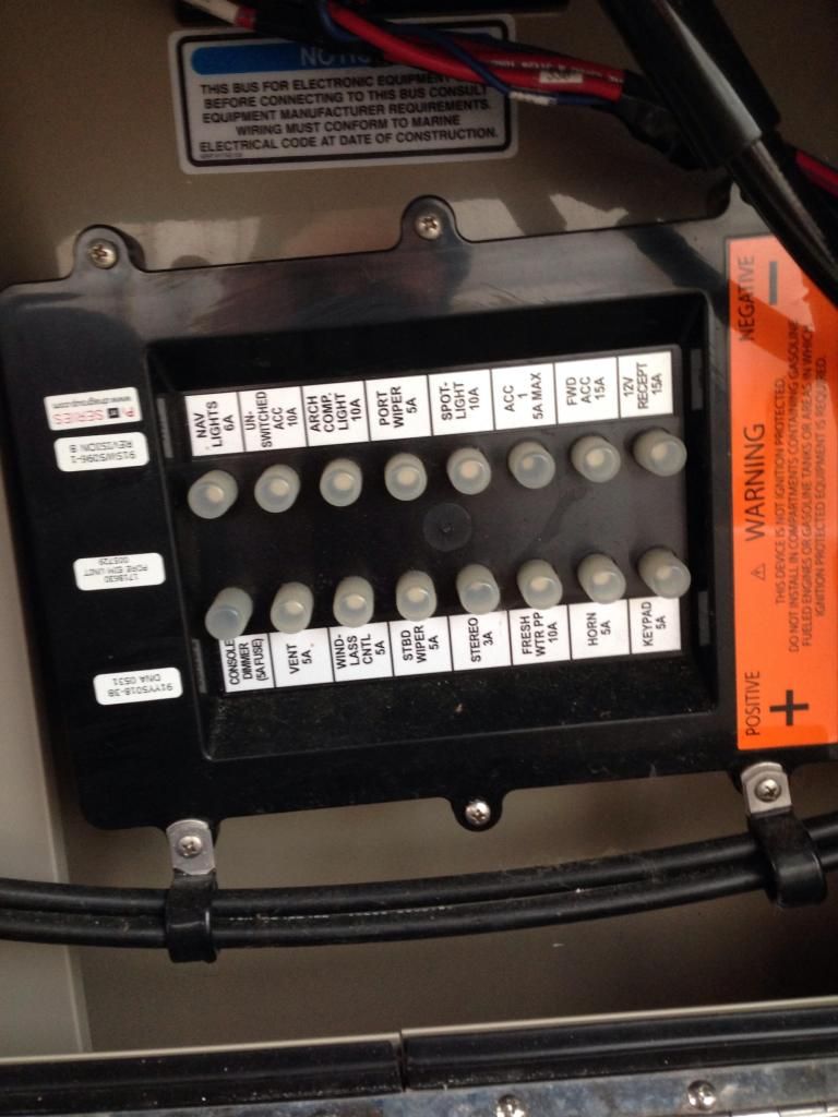
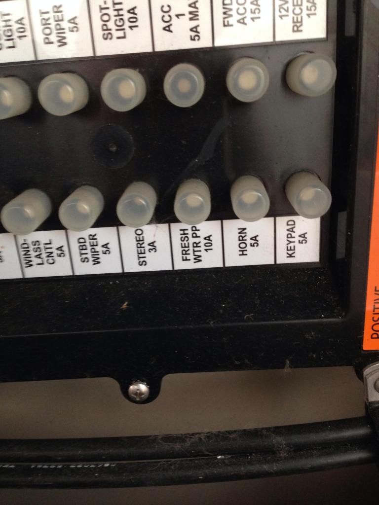
I would like some clarification on these extra circuits I've read about. Can someone show me in the schematics and/or with pictures of the actual EIM where these are? I can't seem to find them in my schematics or boat.

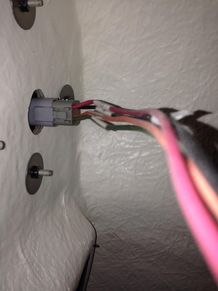
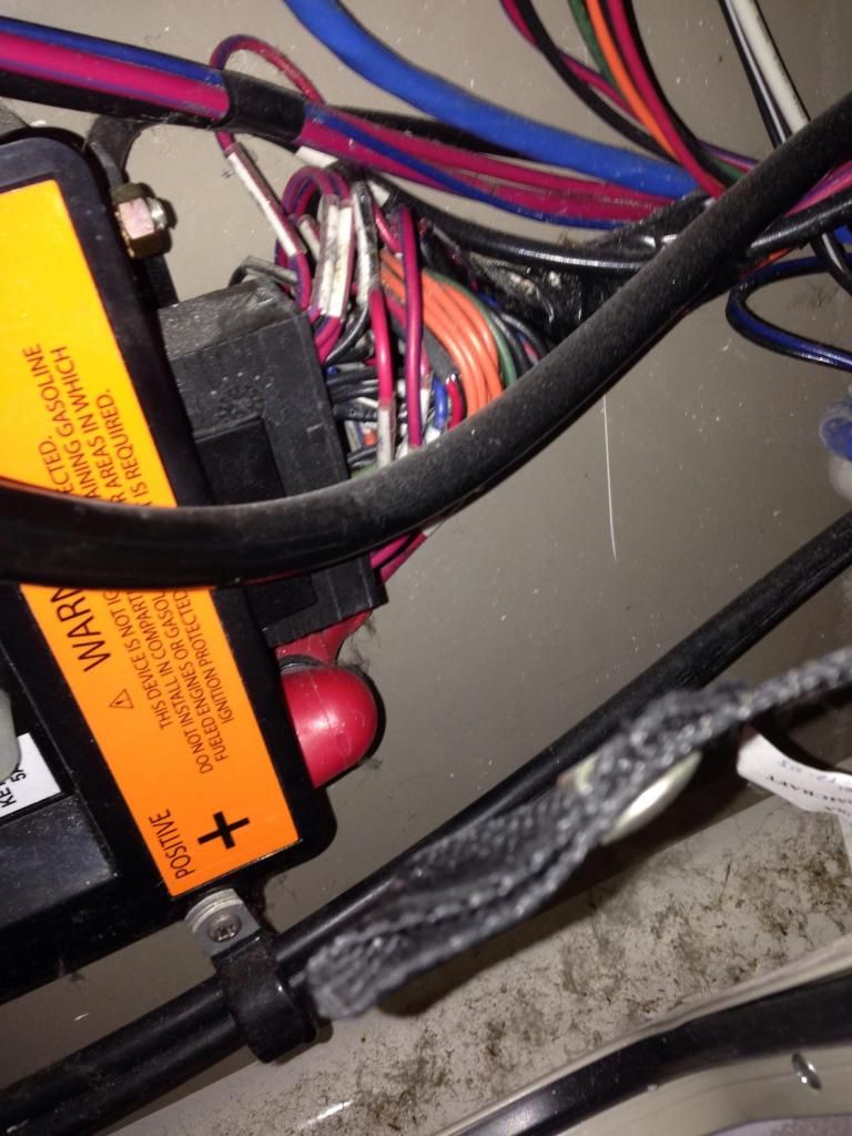
I am particularly interested to know exactly what wire coming out of the EIM is enabled by the unused water pump switch.

Thanks!

Sent from my Nexus 7 using Tapatalk
 
The EIM Schematics are included in your owners manual Supplement. The unused circuits are noted on the schematic and normally read something like "Terminate and Coil". In most cases, the wires were actually run in to the plug and shrink wrapped off several inches from the plug buried in the bundle so they could be tapped on to and used later.

A quick glance at the schmatics for your boat seem to indicate Position #1 on the Forward EIM is what corresponds to the Water Pump button on the Starboard Control Pad. It is marked "UNUSED" so it appears that in the case of this particular circuit, it was not wired like the other spares where it could be used for something else and to answer your question, is not wired to control anything.

The reason all this was done is simple economics. They could order one EIM configuration and one Keypad configuration. Since the wiring harnesses were made custom in the plant they could wire up whatever they needed for a particular boat.
 
Last edited:
I'll have to look at mine again, but the last time I was in that bundle I only found two coiled and capped wires. If the unused functions are wired, I have no idea where they go. Very interesting. Also, the 320 schematics don't show those extra buttons or any additional wiring. Again, interesting.

Sent from my Nexus 7 using Tapatalk
 
CJ,

From what I have seen on the 280 the switches on the switch pad physically connect to a circuit break and relay inside the EIM. Hence the green led lighting and the clicking sound. As far as I can tell, all of the EIM internal output circuits are on the output socket, however the connecting harness plug is not pinned out to utilize them. I know it works on the 280 hatch lift switch/eim. I once entertained the idea of installing a power hatch lift and went as far as to hook up a test light to the EIM hatch pin positions (2&3, 12&13) and the test light lit up when it was supposed to.

Henry
 
Henry,

That is pretty interesting, so you wouldn't need to break into the EIM at all. When you say the harness side wasn't pinned, I'm assuming you mean the actual pins are not in the connector on the harness side. That is not surprising as Merc does the same thing. Figuring out what the right pin is for that connector would be the next challenge.

Sent from my Nexus 7 using Tapatalk

The 280 wiring diagram has a functional circuit diagram that shows the pin position. I would imagine it is the same for the 3xx series as well.

Henry


Sent from my iPad using Tapatalk HD
 
Here's my contribution.

image_zpsdae46a9b.jpg


image_zpsf4d5c6dc.jpg


image_zps92004086.jpg
 

Forum statistics

Threads
113,253
Messages
1,429,352
Members
61,130
Latest member
VaBreeze
Back
Top