
Jimmy Buoy
Well-Known Member
- Dec 3, 2008
- 2,465
- Boat Info
- 2003 Cobalt 293
- Engines
- Twin Volvo-Penta 5.0 270hp & DuoProps
This boat has become a project and a half. It is not consistently idling without stalling once the boat is run for about 10 minutes. At least part of the issue is that the temps don't get over 100 degrees ever and that's verified by an infrared heat gun at the thermostat and the exhaust risers. I'm thinking that the water flow on my engines are not correct.
I've taken both thermostat assemblies off the engine, they both appear to be the same, removed one of the thermostats (which both appear to be closed at room temps) and placed it in 170 degree water. It opened as it should and appears to be working just fine so a stuck thermostat isn't the issue.
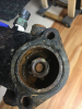
I did find a water flow diagram that describes my situation...

In this diagram, tube #8 is raw water coming thru the fuel cooler which enters the Water Distribution Housing (one large open bowl with one inlet, two outlets, and a drain).
The pressurized water is forced up tube 19 which feeds the exhaust risers. OK.
The other outlet is tube 11, BUT the flow diagram shows water flowing INTO the Water Distribution Housing??? I'm really confused with this as it appears the Water Housing now has two inlets, one outlet and a drain...
In my case, both engines do NOT have tube 9 which seems to just give the ability to drain the block and lower exhaust manifolds via the Water Distribution Housing Drain. The previous owner had added brass valves to the two block drain hoses and there are blue plugs at the bottom of each exhaust manifold. I don't think tube 9 has any other purpose but could be wrong on this.
Tube 4 seems to pull engine water from the block down to the engine's circulation pump, but then tube 12 appears to avoid having its water pulled into the circulation pump and instead heads back to the Water Housing?? How does that happen?
Tubes 5 and 6 should only see water flowing to the bottom of the exhaust manifolds once the thermostat opens - correct? That is the only way water would travel from the lower portion of the thermostat housing to the top where these exhaust water tubes exit.
What am I not seeing here?? Any help would be greatly appreciated!
I've taken both thermostat assemblies off the engine, they both appear to be the same, removed one of the thermostats (which both appear to be closed at room temps) and placed it in 170 degree water. It opened as it should and appears to be working just fine so a stuck thermostat isn't the issue.
I did find a water flow diagram that describes my situation...
In this diagram, tube #8 is raw water coming thru the fuel cooler which enters the Water Distribution Housing (one large open bowl with one inlet, two outlets, and a drain).
The pressurized water is forced up tube 19 which feeds the exhaust risers. OK.
The other outlet is tube 11, BUT the flow diagram shows water flowing INTO the Water Distribution Housing??? I'm really confused with this as it appears the Water Housing now has two inlets, one outlet and a drain...
In my case, both engines do NOT have tube 9 which seems to just give the ability to drain the block and lower exhaust manifolds via the Water Distribution Housing Drain. The previous owner had added brass valves to the two block drain hoses and there are blue plugs at the bottom of each exhaust manifold. I don't think tube 9 has any other purpose but could be wrong on this.
Tube 4 seems to pull engine water from the block down to the engine's circulation pump, but then tube 12 appears to avoid having its water pulled into the circulation pump and instead heads back to the Water Housing?? How does that happen?
Tubes 5 and 6 should only see water flowing to the bottom of the exhaust manifolds once the thermostat opens - correct? That is the only way water would travel from the lower portion of the thermostat housing to the top where these exhaust water tubes exit.
What am I not seeing here?? Any help would be greatly appreciated!
")