Autopilot Not Working

As
Brewster16 - be aware if you have the Ray SmartPilot system which includes an ST8001 head unit there are no cotter pins, rudder actuators, steering rams, rods or other such devices.
There is an electric hydraulic pump that circulates the steering system fluid through the same hoses as the steering wheel and actuates the same hydraulic ram as the steering wheel.
There is a course computer (probably an SG3) that integrates the whole system including the head unit, flux gate compass, GPS receiver, hydraulic pump, and rudder position sensor.
The St8001 is the human/machine interface along with your E120 or other MFD.
The Flux Gate compass is the vessel's immediate directional sensor
The Rudder position sensor is simply that, it senses the position of the rudders.
The GPS receiver provides current location, track, velocity, as well as general directional heading data.

As your ST8001 appears to indicate the system is operating nominally and there are no data errors then it appears the issue is centered around the hydraulic drive elements.

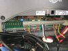
One important test is to measure the voltage going to the AP hydraulic pump when the system is operating; that is measured at the course computer where the pump wires are connected. You should get +12V and -12V depending what direction the system is driving the pump. No voltage then blown 40amp fuse or worse the system has a significant fault. Voltage good but pump not operating then an issue with the wiring to the pump or a problem with the pump it's self.
If your manual steering is working fine then there are no issues with the hydraulics, hoses, or rudder actuator.

That is exactly what I want to do. I have a 12V tester (2 leads and a light) so if power it lights. Where exactly do I attach the leads?
fullsizeoutput_4317.jpeg
 

Attachments

  • IMG_7234.JPG
    IMG_7234.JPG
    157.1 KB · Views: 97
  • IMG_7244.JPG
    IMG_7244.JPG
    209.4 KB · Views: 97
As


That is exactly what I want to do. I have a 12V tester (2 leads and a light) so if power it lights. Where exactly do I attach the leads? View attachment 84401
I think if you look at the labels under the wiring you will find the right two wires are for the AP motor. The two left are the battery power to the system. Remember also that the boat needs to be running on the AP to measure voltage at these two leads.
 
The black and white wires on the NMEA (in your second picture) are curious; most likely the GPS receiver which looks to have been replaced if so.
The first Seatalk connection (3 wires) is for your ST controller (the red wire is power for the controller) and I believe the second Seatalk connection goes to your MFD (no power red wire required).

So, hypothesizing, The two wires cut on the back of the controller may have been originally a Raymarine Seatalk GPS receiver. It failed and they simply cut the wires then installed a new NMEA 0183 GPS receiver and connected it to power and to the NMEA ports on the course computer.
 
Last edited:
Thanks for your input. BTW I did visually check the 40 amp fuse (and all the fuses) which appear to be intact. So, I'm really not that familiar with electronics so can you confirm the following?

I'm heading to the boat with 12V tester and will turn on the "electronics" toggle at the dash as well has the "autopilot" toggle at the dash (powers the autopilot system up at the helm), then remove the cover on the S3G course computer, unscrew and remove the white colored block/protector at the far right which covers the "power" and "motor" wired connections? I will attach one lead on my tester to "motor +" terminal and other lead to "motor -" terminal. I will then put the boat in gear and push "Auto button" on the ST8002 head unit and look for the 12V tester light to come on indicating the course computer is doing its job? And if it is doing it's job then the culprit is the motor itself?
 
Yes I believe you are on the right track. The autopilot needs to be actively trying to change the rudder position (following a track or heading) and thus sending voltage and current to the AP motor in order to do this measurement. The AP motor runs clockwise and counterclockwise depending the direction the AP is directing the rudders; consequently, it will change the electrical polarity to the motor. This is why both of those electrical wires are red in color.
 

Forum statistics

Threads
113,180
Messages
1,428,034
Members
61,088
Latest member
SGT LAT
Back
Top