Air Fittings on SeaWater pump

R-and-R

Active Member
May 9, 2018
258
Boat Info
Boatless
Engines
Boatless
Hello all,

I'm new to big block inboards and learning a lot, many thanks for all of the advice and information here.

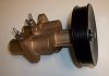
While working on my sea water pump recently, I found that my "air fittings" are a separate component, while on some setups, the air fittings are an integral part of the pump.

What's the function/purpose of these hoojibobbers?
 
Just had my water pump replaced, and had to purchase the one with air fittings, which was twice as expensive (768 vs 400 ish). I don’t know what these are for either. The tech stated he could use the one without air fittings, but then some of the molded hoses,would need to be replaced introducing extra labor and extra parts, so a wash.
 
Couldn’t find a good link, but a search turned up that the air fittings are used for winterization, which is totally worthless in Florida...
 
Are you sure they are air fittings, or are they the standard blue, wing nuts? Wing nuts... you just unscrew them to drain the pump. I would expect to see the wing nuts on an early 496.
 
Welcome to CSR!

The air fittings are used to winterize your engine. Whether the or not they are important depends on where you live. They operate by a small pump that helps drain the water out of the manifolds, risers and heat exchangers.
 
Are you sure they are air fittings, or are they the standard blue, wing nuts? Wing nuts... you just unscrew them to drain the pump. I would expect to see the wing nuts on an early 496.
I have the blue wingnuts also, they are fitted onto the pump housing. In the photo here, you can see a metal tube that runs perpendicular to the water input/output tubes. In my setup, that perpendicular tube is a separate component that sits about 12 inches behind the water pump.
I think PlayDate got the right answer since I have the air blowout system for winterization.
seawaterpump.jpg
 
What a wacky design:

General Information

The air‑actuated drain system uses compressed air to move a piston that pulls a plug out of a drain port or moves a drain tube to expose a hole to a water passage allowing water to drain into the engine compartment. All of the drain locations are arranged to allow any debris to be continually flushed away from the drains during normal engine operation. A feedback mechanism provides positive indication of proper piston movement. When each piston moves far enough in its cylinder, a port is uncovered that allows compressed air to flow back to the air manifold and cause the green indicator to extend. The drains are closed by opening the manual release valve that releases the compressed air from the system. The manual release valve also functions as an automatic pressure relief valve that opens at approximately 482.7 kPa (70 psi), thereby protecting the compressed air circuit from damage due to excess pressure.

Testing ! CAUTION Water can enter the bilge when the drain system is open, damaging the engine or causing the boat to sink. Remove the boat from the water or close the seacock, disconnect and plug the seawater inlet hose, and ensure the bilge pump is operational before draining. Do not operate the engine with the drain system open. !

CAUTION Removing the snap ring from the top of the air‑actuated drain valve can allow the components to come apart forcefully, resulting in injury or product damage. Do not try to repair the valve or remove the snap ring.

1. Remove the boat from the water.
2. Using the hand pump or other air source, pump air into the system until both of the green indicators extend and the manual release valve opens to relieve excess pressure. If one or both of the green indicators have not extended when the relief valve opens, the corresponding air‑actuated drain valve has not opened and may be seized.
3. Release the compressed air from the air circuit by pulling up on the manual release valve ring.
4. Ensure both of the air‑actuated drain valves have closed by verifying that water is no longer draining from either valve. If water continues to drain from an air‑actuated drain valve after the air pressure has been released, the valve is seized and must be replaced.
 
What a wacky design:

Yes it is!

I'm also pretty sure mine won't function properly anyway, I found one of the small plastic lines that connect to that air fitting is damaged. I assume there are more air fittings around the engine for draining the other heat exchangers.
 
I have the blue wingnuts also, they are fitted onto the pump housing. In the photo here, you can see a metal tube that runs perpendicular to the water input/output tubes. In my setup, that perpendicular tube is a separate component that sits about 12 inches behind the water pump.
I think PlayDate got the right answer since I have the air blowout system for winterization.
View attachment 59612
Ah. You have a newer design raw water pump than original (newer than the style that would have originally been on your engine in 2002). That explains it.
 
Ah. You have a newer design raw water pump than original (newer than the style that would have originally been on your engine in 2002). That explains it.

Thank you!

That makes sense. PO made a few other upgrades also, so this may have been part of the package.
 
Thank you guys so much for the information. My case is almost the same, except my new water pump(without air fittings) didn't come with a separate component for air fittings.

How should I deal with the small plastic lines take off from my old pump? Can I just leave them there connect to no where?
 

Attachments

  • pump.jpg
    pump.jpg
    50.8 KB · Views: 164
I have one engine connected (and the air drain system worked great last fall) and one engine where the lines to the sea water pump are disconnected. I used the blue plugs to drain that engine, and stored indoors heated over the winter so I didn't worry. Everything is ok so far but I'm planning to reconnect when I get after replacing the impellers in a bit.
 

Forum statistics

Threads
113,173
Messages
1,427,932
Members
61,086
Latest member
MrWebster
Back
Top