Adding inverter to 2007 310 Sundancer

mobocracy

Active Member
Jun 29, 2014
541
United States
Boat Info
310 Sundancer
Engines
350 Mag & Bravo III
I'm buying a 2007 310 Sundancer that came with a factory generator. We plan to overnight a fair amount on it away from shore power and I'd like the convenience of running AC power for light loads without running the generator every time.

What I'm not seeing in looking at the boat's power panel in the cabin is an obvious way to do it right and easy.

The "right" way (and which matches most maker's manuals) is to feed the inverter as a circuit off the main AC panel and then feed its outputs to a sub-panel which then feeds the outlets/devices you want to power. The downside for this is at least in my 310 is that there's very little room to add a subpanel. Most of the extra space in the "control panel" enclosure is taken up by radio, CD changer, DVD player. I also don't know how much free wire existing circuits have to be moved to a new breaker -- having to rewire existing circuits would be a big headache.

Are the breakers on these panels wired individually (similar to a switch) or on a common snap-in bus like a standard dry land circuit panel?

If they are wired individually (screw terminal bus bar -> breaker -> load) then it would simplify inverter installation a lot -- send the inverter output -> single 20A breaker -> screw terminal bus bar -> existing accessory breaker/switches. I can fit a single 20A pushbutton breaker in the control panel blank space easily.
 
Actually it's not so complicated. Both Shore power and Gen use the same AC distribution panel. The feed to the panel from either is controlled by a lock out switch. One side for gen the other side for shore. The switch is set up is that the two input circuits become mutually exclusive, I.e. The panel is fed by shore, or by gen, but never both.

If you were to add an inverter, you would have to replace the two position switch with a three position. They are made. Although these tend to be rotary style, rather than a toggle style. So the only modification would be the switch mounting. You still would have to observe any switching rules, only switch gen when it's off etc.

Henry


Sent from my iPad using Tapatalk HD
 
Actually it's not so complicated. Both Shore power and Gen use the same AC distribution panel. The feed to the panel from either is controlled by a lock out switch. One side for gen the other side for shore. The switch is set up is that the two input circuits become mutually exclusive, I.e. The panel is fed by shore, or by gen, but never both.

If you were to add an inverter, you would have to replace the two position switch with a three position. They are made. Although these tend to be rotary style, rather than a toggle style. So the only modification would be the switch mounting. You still would have to observe any switching rules, only switch gen when it's off etc.

Thanks for the suggestion. I guess that's kind of the "right" way to feed the whole existing AC panel without much rewiring, although my first question is whether the existing lockout switching for generator & shore are actual switches, or circuit breakers, too. The owner's manual calls them circuit breakers, which means that none of the 3 way rotary switches are exactly a drop-in because they offer no circuit protection.

Since the boat isn't easy for me to access, I can't see how much actual usable blank panel space there is and whether I could fit a secondary panel for inverter specific loads. I think this is probably the best possible method if its practical to move existing loads to new breakers (wire lead length). This eliminates any overload risk and allows whatever's wired to them to automatically switch to inverter power when the generator or shore power are off.

The schematics in the 2007 manual are just ambiguous enough as to whether the main panel breakers are individually wired or snap into a bus like domestic breaker panel do.
 
Your main distribution panel (MDP) has breakers that are individually wired. The genny and shore breakers are wired individually, as well. "Under the skin", they are just larger amp versions of the other breakers in your panel.

Question... Are you wanting to do this to avoid the noise of the genny or to avoid the gas use? If it's for the gas use, you might want to re-think this. The genny uses very little gas and by the time you buy the inverter, probably another battery for the house side, and the odds-n-ends you'll need, you'll have spent much more money than you will likely ever use running the genny.

Depending on how much you anticipate using certain items, maybe just add another battery to the house side and be done with it? Also, changing lights to LED can have a big impact.

Here's a pic of an '06 280DA that I have on the lot (no genny switch). But maybe it will give/remind you of what space you have to work with (whether this looks familiar enough to your 310DA). Also, try looking at boats that are for sale (yacht world, for example). You should easily enough find one that shows the MDP.

https://drive.google.com/file/d/0B3J9JRZY4khnV1RDU29QRDFocTA/view?usp=sharing

Here's one that has a pic of the MDP: http://www.yachtworld.com/boats/200...-3004985/Rogers/MN/United-States#.WIU2p8MrLnA

Worst case... maybe scrap the CD changer? If you don't have it then there should already be a blank space available.
 
Last edited:
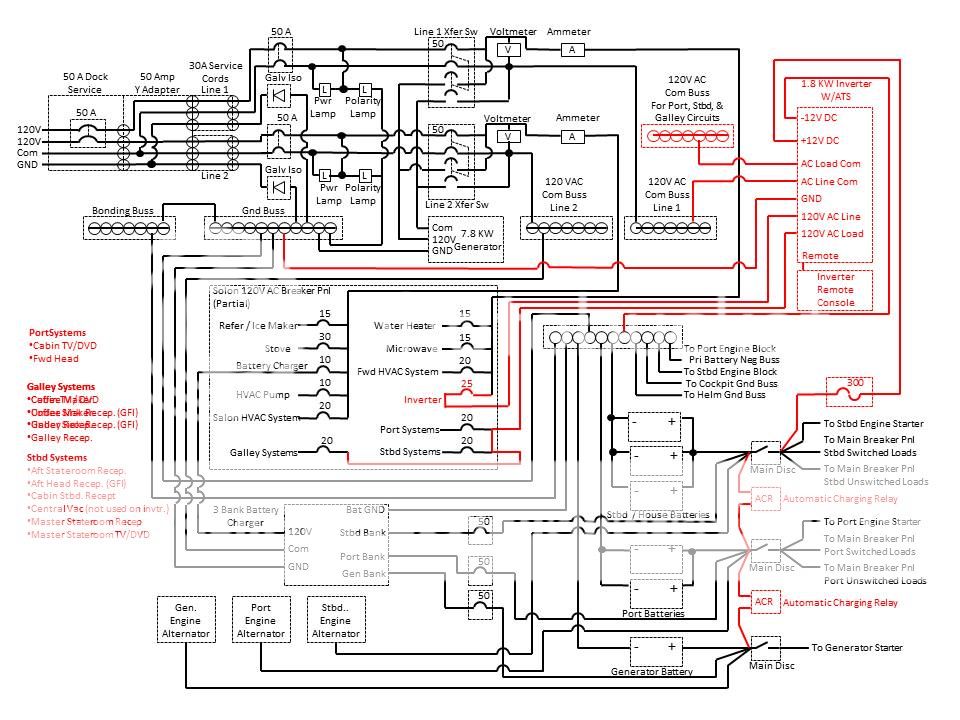
The answer is predicated upon what type of inverter you plan to install (automatic transfer switch on not). Having an automatic transfer switch integrated with the system simplifies things quite a bit. No need for complicated and cautious switching in the below electrical schematic but this inverter has an integrated automatic transfer switch. The inverter and systems the inverter operate do not care if the generator is on or shore power is on or there is no power at all. If power is sensed at the line side then the inverter switches to line power; if power is lost on the line then the load is operated by the inverter and batteries unless the inverter is turned off then - nothing, obviously. This is how my boat is configured and is NEC and ABYC compliant.

http://
 
Last edited:
Your main distribution panel (MDP) has breakers that are individually wired. The genny and shore breakers are wired individually, as well. "Under the skin", they are just larger amp versions of the other breakers in your panel.

Just to clarify even further, typically residential and commercial electric panels have a fixed copper bus that breakers snap into, and the distribution feed is screwed to a terminal that runs out of the panel. Are you saying the Sea Ray MDP breakers are wired more like a switch, with a screw terminal supply and distribution output?

Question... Are you wanting to do this to avoid the noise of the genny or to avoid the gas use? If it's for the gas use, you might want to re-think this. The genny uses very little gas and by the time you buy the inverter, probably another battery for the house side, and the odds-n-ends you'll need, you'll have spent much more money than you will likely ever use running the genny.

Partly convenience of having low-power incidental 110v items always on (laptop, phone charger) and partly to avoid the general wear and tear on the generator. I will need to run it a certain amount for the cockpit grill, air conditioning, and possibly battery topping if we drop the house batteries much, plus you need to exercise a generator a certain amount anyway. I just see an inverter as generally providing a certain convenience and skipping some short-run stop/start cycles on the generator.

Depending on how much you anticipate using certain items, maybe just add another battery to the house side and be done with it? Also, changing lights to LED can have a big impact.

It already has two house batteries, although they look smaller than the start batteries and I would probably go with larger versions. I'm guessing on any used boats it makes sense to drop in new batteries anyway given that the odds are the existing cells are probably half through their life anyway if not slightly abused by storage during the brokerage phase of their life.

Also, try looking at boats that are for sale (yacht world, for example). You should easily enough find one that shows the MDP. Worst case... maybe scrap the CD changer? If you don't have it then there should already be a blank space available.

I have good high resolution photos I took of the MDP, so I know what the front looks like and the relative available space. It's the nitty gritty of the back of the panel that's a mystery. Dumping both the CD changer and the double-DIN satellite radio head unit for a single-DIN head unit isn't a bad way to get needed panel space back, either, provided I can get one that works with the existing remote controls. I don't need satellite radio and the iPod connectivity the head unit offers is probably obsolete, and new unit would almost certainly provide Bluetooth connectivity.

Going new single-DIN radio would give me ample space for an inverter subpanel and even the remote control panel for the inverter.
 
The answer is predicated upon what type of inverter you plan to install (automatic transfer switch on not). Having an automatic transfer switch integrated with the system simplifies things quite a bit.

Yeah, the inverters I've looked at are all automatic transfer -- they don't care if the line source is shore or generator and switch to battery when either is missing.
 
Correct - the SR breakers do NOT click into a bus bar like they do in a home's panel.

Side note... I have not had the panel apart in your model, but in all the ones I have, there is typically more room in the "box" than there is in a home's panel. Although there really isn't a "box" in the Sea Ray, like you're used to in a home setup. The 110V side usually just has some type of shield over the wiring.

If you go with a new radio, it's likely going to be Bluetooth so you really wouldn't need the wired/dash remote?
 
I'm for the upping the ante on the house batteries and going to LED's. 4@6VDC golf cart batteries should be plenty of amperage for what you plan on running. As for the gennie, they need to be used and used hard to keep running. I don't know why. I've also never seen a properly maintained one fail from use.
 
Correct - the SR breakers do NOT click into a bus bar like they do in a home's panel.

Side note... I have not had the panel apart in your model, but in all the ones I have, there is typically more room in the "box" than there is in a home's panel. Although there really isn't a "box" in the Sea Ray, like you're used to in a home setup. The 110V side usually just has some type of shield over the wiring.

That makes the whole thing a little easier to work with. It might even be possible to feed the existing breakers I want tied to the inverter directly from the inverter output if they can be wired individually, although something makes me think this violates some rule or other although it seems like it would make complete sense and not present any problem other than troubleshooting confusion to someone who didn't know about the inverter. The MagnaSine M2000 series even seem to directly support this kind of an install with their single in, dual out configuration -- I figure "outlets/refrigerator" and "microwave" are the main two circuits I want tied to it. Nothing else on that panel makes sense to run of inverter power even if it could be done.

If you go with a new radio, it's likely going to be Bluetooth so you really wouldn't need the wired/dash remote?

Call me crazy, but I think there are two remotes on this boat, one on the swimdeck and one on the dash, and they will control more than Bluetooth does, like volume and for adjusting the actual radio. If I swap the head unit out, I guess since the remotes are there I'd rather bias towards maintaining their functionality. If anything I need to turn my kid's crappy pop music down without getting out of the water!
 
That makes the whole thing a little easier to work with. It might even be possible to feed the existing breakers I want tied to the inverter directly from the inverter output if they can be wired individually, although something makes me think this violates some rule or other although it seems like it would make complete sense and not present any problem other than troubleshooting confusion to someone who didn't know about the inverter. The MagnaSine M2000 series even seem to directly support this kind of an install with their single in, dual out configuration -- I figure "outlets/refrigerator" and "microwave" are the main two circuits I want tied to it. Nothing else on that panel makes sense to run of inverter power even if it could be done.

This is the back of the 400DA AC power breaker panel. Pretty common configuration with Sea Ray. The breakers are typical marine units. Note that all I did is to add a new breaker (bottom left in picture - that was a spare position) which is the line power to the inverter. By lowering the two copper buss bars off the two upper left and one upper right circuit breakers and then tying the inverter load side to these three, the inverter now provides power to these circuits. It's all simple and seamless and can easily be converted back to as original.
 
Last edited:
This is the back of the 400DA AC power breaker panel. Pretty common configuration with Sea Ray. The breakers are typical marine units. Note that all I did is to add a new breaker (bottom left in picture - that was a spare position) which is the line power to the inverter. By lowering the two copper buss bars off the two upper left and one upper right circuit breakers and then tying the inverter load side to these three, the inverter now provides power to these circuits. It's all simple and seamless and can easily be converted back to as original.

Thanks for that picture. That's exactly how simple I hoped it would be, and totally avoids the addition of a subpanel. Feed from AC panel accessory slot to inverter input, and migration of existing circuits to inverter output.
 
i don't mean to hijack but this is a timely thread for me.....I have a 2000 watt inverter I want to install on my boat to power my 110VAC outlets when there is no shore power and no generator power....I like the idea of an automatic transfer switch that detects the presence or absence of power to automatically control the inverter....

however i am a novice when it comes to electrical projects...I understand the basics and have done a few minor wiring projects so the concepts are not entirely foreign to me.....

if anyone that has added an inverter to their boat (or anyone that just knows how to do this) would care to take the time to provide a detailed set of instructions to the OP on this thread or to me offline it would be very much appreciated....pictures are always a plus if available...

maybe these instructions can become a 'sticky' for others that follow that want to do the same project....

thanks in advance.....

cliff
 
Last edited:
Mobo, just offering this as some more "thinking" information...

All inverters will use more battery power than they give out as some energy is lost to the transfer/change from DC to AC. That's nothing new and probably common knowledge. Obviously the microwave won't work on DC, but various device chargers can be run via 12V (laptops are actually charge via 12V... that big "block" in the cord changes 110V to 12V). The fridge can be run very efficiently on 12V, too. Changing 12V cabin and cockpit lighting to LED's can have a big impact, along with the anchor light for overnights. As an example, I once went 3 nights and 2 days on ONE group 27 DC battery - used lights, some radio, charged phones, the fridge the enitre time (even trailering to and from the water), anchor light each night... Ran the engine for less than an hour over the whole weekend... still started the engine the last day like normal. Quite honestly, I was surprised - but I did it to test things out and see how it would work.

I'm mentioning this not to try and change your mind, but more-so just in case you weren't aware of how long you can really go on just battery power. Using the inverter for things that can be otherwise accomplished via DC, though, will actually use up your battery supply faster.
 
Thanks for that picture. That's exactly how simple I hoped it would be, and totally avoids the addition of a subpanel. Feed from AC panel accessory slot to inverter input, and migration of existing circuits to inverter output.

Remember also that the neutrals (common) on the inverter load circuits must be "re-landed" to a new terminal strip that connects to the inverter load side neutral. The inverter's ATS switches the neutrals also. This is very important for both safety and to keep the GFCI's from tripping. See schematic that I posted earlier.
 
Mobo, just offering this as some more "thinking" information...

All inverters will use more battery power than they give out as some energy is lost to the transfer/change from DC to AC. That's nothing new and probably common knowledge. Obviously the microwave won't work on DC, but various device chargers can be run via 12V (laptops are actually charge via 12V... that big "block" in the cord changes 110V to 12V). The fridge can be run very efficiently on 12V, too. Changing 12V cabin and cockpit lighting to LED's can have a big impact, along with the anchor light for overnights. As an example, I once went 3 nights and 2 days on ONE group 27 DC battery - used lights, some radio, charged phones, the fridge the enitre time (even trailering to and from the water), anchor light each night... Ran the engine for less than an hour over the whole weekend... still started the engine the last day like normal. Quite honestly, I was surprised - but I did it to test things out and see how it would work.

I'm mentioning this not to try and change your mind, but more-so just in case you weren't aware of how long you can really go on just battery power. Using the inverter for things that can be otherwise accomplished via DC, though, will actually use up your battery supply faster.

Thanks, I appreciate the advice. Right now this is a future project and I will probably get the first season out of the boat without adding an inverter and see if I "miss" it. I suspect I may just not feel the need for it.
 
Very timely thread. I'm trying to navigate a DIY inverter install on my 2007 40DA. The install guide on the 1800W XANTREX model I'm looking at says explicitly that you must not have a DC input cable more than 5' long. This would require the inverter to be installed in the engine room.

1) Ive heard these inverters can "spark" during switching, and that the best practice is to keep out of the engine room.

2) If installed in engine room and wired directly to the house bank of batteries, how can the inverter be disconnected without having a breaker inline requiring engine room access to power down?


I had envisioned powering the inverter from the load side of the main disconnect (as depicted in the above schematic) but this would seem to violate the "no longer than 5' and 1/0 AWG supply wiring requirements.

Any advice?

I installed mine in the storage compartment in the cockpit above the batteries. I mounted it on a board with a battery switch so i can shut it off. It's not wired into the AC yet. WHen I use it, I simply run a shore power cord from the inverter to the shore power inlet. It's a bit "bush league" (thats Canadian for red neck), but works till I hard wire. I may upgrade the inverter at some stage but this works for the basic 110 I need while on the hook.
7F7679DA-7257-434A-B8CA-79BF19F8ABD5.jpg


00000000-0000-0000-0000-000000003678.jpg
 
Very timely thread. I'm trying to navigate a DIY inverter install on my 2007 40DA. The install guide on the 1800W XANTREX model I'm looking at says explicitly that you must not have a DC input cable more than 5' long. This would require the inverter to be installed in the engine room.

1) Ive heard these inverters can "spark" during switching, and that the best practice is to keep out of the engine room.

2) If installed in engine room and wired directly to the house bank of batteries, how can the inverter be disconnected without having a breaker inline requiring engine room access to power down?


I had envisioned powering the inverter from the load side of the main disconnect (as depicted in the above schematic) but this would seem to violate the "no longer than 5' and 1/0 AWG supply wiring requirements.

Any advice?

Unless the inverter is hazard rated then it should not be in the same compartment as the engines in a gasoline powered boat. Diesel does not have the same requirements.
Cable size is dependent upon length. You need to do an ampacity calculation to determine what is needed. The manufacture provides a guide. This is a good guide on cable sizing https://www.bluesea.com/resources/1437

This is the inverter installation on my 400DA. Note that you must put the circuit's fuse as close to the power source as practical.
 
Last edited:
Very timely thread. I'm trying to navigate a DIY inverter install on my 2007 40DA. The install guide on the 1800W XANTREX model I'm looking at says explicitly that you must not have a DC input cable more than 5' long. This would require the inverter to be installed in the engine room.

1) Ive heard these inverters can "spark" during switching, and that the best practice is to keep out of the engine room.

2) If installed in engine room and wired directly to the house bank of batteries, how can the inverter be disconnected without having a breaker inline requiring engine room access to power down?


I had envisioned powering the inverter from the load side of the main disconnect (as depicted in the above schematic) but this would seem to violate the "no longer than 5' and 1/0 AWG supply wiring requirements.

Any advice?

Is the 1/0 supply wiring a limitation of the terminal on the inverter? If you can use a larger gauge of wire you can get away with a longer wire run. I was looking at MagnumEnergy inverters and they will accept up to 4/0 wire. Blue Sea systems has a wire gauge calculator that will help tell you what wire size you need for a given ampacity, wire length and a few other variables.

Many inverters have a control panel option that seems like a desirable option, allowing monitoring of batteries, load and remote shutdown. Apparently many inverters are not rated for engine room install, but even without that the inverter is likely to be in an awkward location for manual shutdown anyway.
 

Forum statistics

Threads
113,193
Messages
1,428,281
Members
61,104
Latest member
Three Amigos
Back
Top