Westerbeke Generator wiring to remote start

Clutch1956

New Member
Jul 27, 2017
13
Boat Info
Sea Ray 1997 370 SD
Engines
7.4 mpi
Hi all,

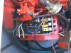
I have a big ask of someone. Will pay someone for their time. I have replaced a Westerbeke 7.0 BCG with a 6.5 BCG and trying to get someone to wire it back up the boat has proving to be a task. So call Westerbeke mechanics won't even try because they said the wires are not marked (well if they were, I could do it). They are color code so would need pictures that are clear to show that. I am asking if anyone would be willing to take some detailed pictures of inside the generator's control panel (the one that sits on the generator), pictures of the wires in the backend that attach to the Stator come out then to inside the circuit breaker. The work would consist of removing three covers and taking pictures.
The boat is a 1997 Sea Ray Sundancer 370 with a remote start panel in the cabin, the one with two buttons not the three. Or if some knows of a good Sea Ray/Westerbeke mechanic in the Mass, Rhode Island area that would be able to figure it out. The wiring diagrams only take me so far. I figured out a few wires but not all.

Thank you for any and all help,
Bob
 
I had a heck of a time when I removed my boat's genset. The Westerbeke diagram showed one more wire than what SeaRay used. I guess Sea Ray was trying to save a dollar and spent some engineering effort of reducing the wire count required for the remote panel. I had to diagram out the switches and reverse engineer what they did.

Reverse engineering the wiring isn't too hard. You have to match up the switch contacts and indicator lights with the terminals and diagram in the manual. Most repair techs won't have that information and won't want to reverse engineer Sea Ray's sometime unique wiring. Your dealer might be a little more helpful.

If you want to do it yourself, pull the remote panel and diagram which wire colors are connected to which switch contacts. Then overlay that on the remote panel wiring to find the right color combination.
 
Thanks for your response and suggestion. I wish I was confident enough to do what you suggested. I am close to understanding which wires goes where, but not 100%. That is where I need guidance before I start it and due any damage. Sea Ray did do their own wiring engineering by the looks of it because it doesn't completely match what Westerbeke has.
 
I'm surprised any Westerbeke mechanic would say that. The wiring, at least what is in their respective manuals, is the same (5 wires):
7.0
7.0 Westerbeke.jpg

6.5

6.5 Westerbeke.jpg
 
In 2013 I replaced my 2001 7.2 BC-something with a 2013 7.0 BCGD Low Profile and it was plug-n-play. ie: the plug that was removed from the old gen fit right back into the receptacle in the new one. The only problem I have is that if it shuts down/stalls there's no alarm at the helm.

Hansen Marine (Marblehead, MA) is the distributor for the NE. Have you called them and tried picking their brains with this question? As for who is an authorized WB service place, there ain't that many and you are beholden to them. You may have to pay through the eyeballs to get this resolved but I'll bet no one else would try it. I've learned that gas WB generators are like Holy Water to a vampire in the eyes of most marine mechanics.

Did you purchase the genset new? From where? Can they help?
 
Good luck. My mechanic gave up. I now have a panel behind the battery switch and breaker door.
 
Post a photo of the back of the remote start switch panel that clearly shows the connections and wire colors. Shouldn't be too hard to figure out the wiring with that information.
 
Please post your gens terminals your needing to wire.
I’ll see if it’s the same as my 7.0 BCG that I just replaced the electrical back end on.

I could check over the weekend.
 
Thank you all for your willingness to help. I think I am getting close. I have posted some pictures and diagrams in hopes that it helps. It has been a real eye opener as to how many Mariners advertise doing this type of work and then say they can't or won't we you bring it to them and they don't see plug and play. Why would you need a mechanic for plug and play...

1. I believe I have the circuit breaker part sorted out except for one wire that goes to the engine (Picture-From motor to breaker.jpg) that is a picture from my 7.0 gen before removal. Don't know where that Orange wire goes. On the 6.5 genset it is Red but I think is the same wire.

2. PDF file of a drawing I did of the remote panel wiring. As you can see there are different color wires than in Westerbeke's diagram because of Sea Ray's wiring or someone's due to two rockets vs three. Also a picture of the Back of the Panel showing the wires. I have the Yellow and White w/red stripe wires marked where I think they go, just not positive. The Green one no idea.

3. Picture of the wires that come from the remote panel to the genset. Those three; White w/red stripe, Green and Yellow are the ones in question. Also the Red wire that is hanging off the box at the bottom of the picture that I think goes to somewhere in the breaker or not that I referred to in 1.

4. The Red and Purple in the control box was there. I think the Purple goes to the Yellow. Red one no clue, it appeares to have had a fuse on it..wondering why?
I have attached 4 files. In need more please let me know.
From motor to breaker.JPG
Back of Panel.JPG
 

Attachments

  • My drawing of Remote Panel backside.pdf
    20 KB · Views: 263
  • Remote Panel to Genset.JPG
    Remote Panel to Genset.JPG
    178.6 KB · Views: 688
I uploaded a clearer/neater wiring diagram of the Remote Back Panel.
Just as a side note The wiring harness coming from the remote panel to the genset has 6 wires not 5 as in Westerbeke's diagram. Again, may be because of two rocker switches instead of three.
Colors:
Green
Yellow
Black
White w Red stripe
Red w Purple
Yellow w Purple
 

Attachments

  • Back of Panel.pdf
    18.3 KB · Views: 313
FYI,
After looking closer at the orange wire that goes from the gen. wiring harness into the breaker box it appears to pass through the box and attach somewhere on the stator.
 
I replaced my Quicksilver 7.5 years ago with a Westerbeke 7.0. The Quicksilver had a two button arrangement and I stuck with that. I will take a look at the panel later today and confirm your wiring.
 
I replaced my Quicksilver 7.5 years ago with a Westerbeke 7.0. The Quicksilver had a two button arrangement and I stuck with that. I will take a look at the panel later today and confirm your wiring.
Awesome, Thank you
 
Please post your gens terminals your needing to wire.
I’ll see if it’s the same as my 7.0 BCG that I just replaced the electrical back end on.

I could check over the weekend.

Thank you, I posted some pictures, diagrams and updates.
 
Post a photo of the back of the remote start switch panel that clearly shows the connections and wire colors. Shouldn't be too hard to figure out the wiring with that information.

Thank you, I posted some pictures, diagrams and updates.
 
I'm working on this now. Part of the issue is we have different switches.

My PreHeat is a momentary switch which closes a connection. Yours has two more terminals on it with wires attached.

My Start-Run-Stop switch is momentary Start, rests at Run and is OFF at Stop. I have 5 terminals on that switch of which 4 are used.

The harness I used was from Westerbeke and it required a little trial and error to get it functioning with two switches instead of three (I also replaced both switches). For the most part, it matches up with the following schematic.
Remote Westerbeke harness.jpg
 
Last edited:
Can you post a photo of the front of the switch panel? I need to sort out how the switches are working then it should be pretty easy to identify the wires.
 
Also it just may be easier to replace the switches. They are available at West Marine.
 

Forum statistics

Threads
113,114
Messages
1,426,320
Members
61,027
Latest member
NeilS
Back
Top