Location of Fuse in Nav Light Circuit (1994 270DA)

gengiant

New Member
Oct 5, 2006
268
Sacramento, CA
Boat Info
1994 270 DA
Engines
7.3L BRIII
Hey all,

I just got done reading the thread about the inverter install and was amazed at the collective wisdom represented by this esteemed group - my hat's off to all of you! :smt038

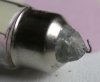
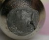
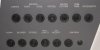
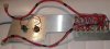
Maybe you can help me out with a little electrical problem on my 1994 270 DA? Here's the story: last weekend I was anchoring out for the night and plugging in the anchor light stem at the top of the windshield. When I flipped the switch to the anchor light position, only the front light bulb of the 2 bulbs in the stem came on. :smt017 From the helm I could see that the bow nav lights were working in the nav light position of the helm switch. So I figured that I might have some contact/corrosion issues at the plug for the anchor light stem. After some back and forth of the stem I tried the light switch again. This time none of my lights worked. :smt021 So I figured I had a short and blew a fuse or a circuit breaker. Well. I couldn't find either. Do any of you have a clue to what's going on or any ideas where the fuse for this circuit is located? :smt100

Thanks!
 
Thanks for the welcome, Wesley! This forum is truly turning out to be a blessing! And yes, I feel realy stupid now! :smt021 Part E-43 clearly identified in the parts manual. DUH! And to think that I keep a copy of the parts manual on board for just that purpose. :smt101 I totally forgot that I do. I just don't have very many things go wrong with my boat, at least not things that I don't mind trying to fix myself.

Well, now that I realize where the fuse is located, I still need to trace the cause of it blowing. Any thoughts anyone? (Note: it was a dry night when this happened, so I doubt there was water in the light mast plug/socket causing the short.
 
I have a 1996 270 which I would thing is wired very much like yours.

As far as I know, there is no fuse, only circuit breakers. I think you have already discovered the location of the circuit breaker in question, it is on the circuit breaker panel at the helm. I have not tripped one of these breakers, but I would think that if tripped it would pop out, and you could push it back in to reset it.

I suspect the source of your trouble is with the anchor light mast or base or bulbs. You could try resetting the circuit breaker with the nav lights off. Then, with the anchor light mast removed, turn on the nav lights. If the circuit breaker trips, then the problem is not with the mast that is not installed. It could still be in the base, or be elsewhere in the boat.

If the breaker does not trip, and the nav lights work, then turn the nav and anchor lights back off. Install the anchor light mast, and turn on the anchor light. See if the breaker holds. If it does, for a minute or more, then turn on the nav lights and see what happens.

Both positions of the anchor/nav light switch are fed with one wire from the single circuit breaker. That particular switch has two outputs, of course; the anchor light and the nav lights.

This thread belongs in the electrical section.
 
Dave,

Thanks for the suggestions! When I read the thread on the inverter install your knowledge already impressed me. And you are correct, your '96 and my '94 are very similar. Mine is freshwater-cooled as well (closed cooling circuit), except that is was repowered in 2000 with a 330 hp 7.4l Mercruiser. And then in 2001 the BR III outdrive was completely rebuilt from the ground up, as the previous owner hit a submerged piling. The admiral and I absolutely love our boat, though she's intimidated by the boat's size when it comes to driving her. This winter/spring I am planing on a couple of projects such as installation of a raw water washdown pump and hose bib, installation of a small microwave and then, of course, some general annual maintenance, though I may have MarineMax "assist" with that one (I've got an annoying transom leak that I hope they can fix - see my new thread re "pivot pin bushing").

Cheers!
 
I just had a similar problem with my bow and stern (anchor) lights. Sometimes both or all would work, and sometimes when I plugged the stern stem in some lights would go out.

After plenty of :smt021 I narrowed it down to the stern light base having a short. Replace the base and the problem was fixed :smt038
 
Mike,

Good suggestion! I have been eying the light mast socket for some time, seeing that the contacts do show signs of corrosion. Does anyone know if there's a cap one can use to plug the socket with when not in use to protect the contacts from the elements?
 
gengiant said:
Does anyone know if there's a cap one can use to plug the socket with when not in use to protect the contacts from the elements?
Yes, assuming you have that goofy socket on the windshield like I do - Perko makes a black cap that screws on. Found one in some Mom&Pop shipstore several years back.
 
GG, if you have a digital multimeter, here are a couple of checks you can do. These are what I found when I went and checked my boat, I assure yours is the same.

With the light mast removed, you can check for the proper voltage at the base mount on the top of the windshield.

The center pin, towards the front, is the ground, and should measure a low resistance to ground. Less than an ohm would be good.

The starboard pin in the base is for the front all around light, and should measure battery voltage with the switch in either anchor or nav position.

The port pin in the base is for the rear facing anchor light, and should only measure battery voltage when the switch is in the anchor position.

With the anchor/nav switch in the off position, I measured about 20 ohms to ground from both the port and starboard pins.

You can do resistance checks on the mast itself. The lamps at the top are 12V 10 watt lamps, and measure about 1.2 ohms. If you measure from either outside pin to the center pin, you should read the 1.2 ohms or a small bit more. When I actually did this measurement, I got about 60 ohms on one side, and not a stable reading. I took the top cap off, removed the lens, and wiggled the bulbs. The reading changed.

I removed the bulb with the high 60 ohm resistance, and found one metal end cap loose. I think the glass itself and the wires are still intact. However, the wire stick out through the end of the metal caps, and appear to be bent over against the cap and fasterned there with a conductive paste glue. One end looked like a typical cold solder joint, where the wire is pokes through the solder but is not bonded to it. But the material does looks more like an adhesive than a solder. Here are photos.

The problem pictures would simply cause the lamp to not light. It would not cause excess current flow or blow a fuse or breaker.
 

Attachments

  • dscn8554-crop_202.jpg
    dscn8554-crop_202.jpg
    25.4 KB · Views: 1,535
  • dscn8552-crop_186.jpg
    dscn8552-crop_186.jpg
    38.8 KB · Views: 1,533
mrtopknight said:
I just had a similar problem with my bow and stern (anchor) lights. Sometimes both or all would work, and sometimes when I plugged the stern stem in some lights would go out.

After plenty of :smt021 I narrowed it down to the stern light base having a short. Replace the base and the problem was fixed :smt038

I would expect that if you have a short in the wiring, then you should cause a breaker to trip. If it did not trip, then it certainly could cause any other lights on the same circuit to get almot no volts, and not light.

In the process of chedking how my system works to get the data above, I decided to try and pop the nav light circuit breaker by shorting the anchor light pin to the ground pin in the socket at the top of the windshield with the light switch on. So I shorted them togther with a screwdriver for a second or two. The breaker did not pop out, and the lights still worked when I put the mast back on. So the protection is not as well designed as it could be if it can't detect a short circuit in the wiring.

Granted that the wires may be small, have multiple connectors to go through which add resistance, any breaker has some sort of a time delay vs overcurrent curve for tripping, and I did not leave the short on forever.

Having seen what I saw, I am not surprised at what you describe happened to you.
 
Ok, I've printed out all of your good advice and will see if I can trace the problem with a multi-meter. I've actually got to take some time to trace a couple of other 'minor' electrical problems such as the port windshield wiper not working, etc. Your suggestions now actually have me thinking that I might be able to fix the problems! :grin: We'll see.

Thanks again! I'll post results in a few weeks (with Thanksgiving coming quickly, it'll be a month or so 'till I get to be with my boat again. :smt009 )
 
GG,

Here is a cropped picture showing the breakers in my breaker panel below the helm. I would think yours is the same. You can see that the port and stbd wipers each have their own breaker. The input side of the breakers are all wired in parallel, except for the ignition breaker. The output side of the breakers then have individual wires that send power to the switch panel.

It is certainly possible, but maybe unnecessary, to unscrew the breaker panel and measure that you have battery voltage on the output side of the breaker. It is easy to tell the input side from the output side. The input side has a wires running from breaker to breaker. The output side has a separate wire from each breaker that runs back behind the console.
 

Attachments

  • dscn4052-640-brkrpnl_174.jpg
    dscn4052-640-brkrpnl_174.jpg
    24.6 KB · Views: 1,489
Dave,

There you go again, giving me more GREAT advice! :thumbsup: I really appreciate it. Now I just need to make time to work on the boat. Unfortunatly, I don't have room at the house and thus have to keep her in a storage yards 5 miles away. Oftentimes, this makes working on her for the intermittent hour or so nearly impossible. But at least, it's a "labor" of love. :wink:
 
GG,

If you were to remove your breaker panel and lay it down on the seat (don't really do it), it would look like the photo below. Well, actually, the rats nest wiring would have to be cleaned up and tidied up first, but you get the idea.

There is a single bundle of wires that go from the breakers in the top row to a single connector. That connector then mates to a connector from the switch panel. So both wipers get their power through this wire bundle and connector. The connectors are about the same quality as you would find in a PC. It is possible to lose electrical connection going through the connector; either because of corrosion or a pin pushed out in the plastic body.

Likewise, all the breakers in the bottom row that feed positions in the switch panel have a common wire bundle and a common connector that mates to another connector from the switch panel.

So that is the story of how power gets from the wiper breakers to the wiper switches.
 

Attachments

  • dscn4070-brkrback-750_105.jpg
    dscn4070-brkrback-750_105.jpg
    38 KB · Views: 1,471
Dave,

Did you rewire your panel yourself? Wow! It bears no resemblance of the rat's nest found behind the panel on my boat. You obviously spent a ton of time with your boat's electrical systems. Very nice!

Maybe you can then answer another question to help me solve another electrical problem. Well, this may not even be an electrical problem. Are you familiar with the cockpit light on the starboard side of the little depressed step right in front of the cabin slider? It has a little downlight press-fit into it, which is being fed from behind. Well, when I popped that light out of the fiber glass I was looking at a barren hole - no bulb and connecting wires going into the downlight fitting. I am hoping there is access somehow to this space behind the cockpit wall, presumably from the engine bay side? But if I am not mistaken, the water tank sits smack in front of this 'space', correct? Just my luck! Any good ideas of how I might be able to find this bulb and wires? Ive tried to see them through the little light hole, but couldn't locate them. I am thinking I may have to use a piece of wire and fish for them through that little hole.
 
GG

Again, in my boat, here is what happens with the wipers at the switch panel. From the above, you know that there is a separate wire coming to the switch panel from a 6 pin connector for each wiper. The wire color for the port wiper in my boat is orange with red tracer. The wire color for the stbd wiper is orange with a green tracer.

Both wires leaving the switch panel headed to the wipers go out through a fifteen pin connector, arranged in 3 rows of 5 pins. The wire colors are the same as the input side. The port wiper pin position is column A, pin 2. The stbd wiper is column C, pin 3.

From the other side of the 15 pin connector they somehow find their way to the wiper motors. I have not traced those wires out.
 
Dave,

I must admit that I hope not having to trace this wire between the fuse panel and the switch panel. What you describe so 'matter of factly' and straight forward is in sharp contrast to the mess and tangle of wires behind my braker panel and especially behind my switch panel. I just had to replace my bilge blower switch, so I needed to take the switch panel off. Thankfully, that repair was simply and un-plug and plug excercise. Well, until I go through the analysis you described with the multi-meter, I am hesitant to even try and guess where the problem lies. Who knows. It may be as easy as the wiring in the window frame. About a year ago I lost power to the same port wiper. I had them fix it when the boat was in for it's annual service last winter. They said hat someone (the prior owner maybe) had run a screw from the bimini frame right through the wire running in the window frame (covered by a strip of rubber gasketing). Who knows? Maybe their repair "fell apart"? The first thing I will be checking is to see if there is power at the wiper motor itself. If not, I will go back to the switch, then the fuse and so on. Too bad they have rain forecast for this area through this weekend. Thanks to your help I am now actually looking forward to tackling these issues (wiper motor and nav lights). Thanks again!!
 
gengiant said:
Dave,

Did you rewire your panel yourself? Wow! It bears no resemblance of the rat's nest found behind the panel on my boat. You obviously spent a ton of time with your boat's electrical systems. Very nice!

Yes and no. I did not rewire it in the sense of replacing wires. They are the same wires. But I did spend a lot of time untangling the mess and laying it out in a logical fashion and then taping them into wire bundles as you can see.

I have never found a wiring diagram for my boat, and I wanted to be able to figure it out. That was not possible with the rats nest. Plus I needed to understand the wiring as I had a broken depth sounder and VHF that I wanted to fix, and I added a trim tab indicator that needed power. The VHF I fixed, the sounder I think has a dead transducer and is not repairable.

I now have wiring diagrams for the breaker panel and the switch panel. If you need a copy, I could send you a jpeg image. They would be too large to post here.

gengiant said:
Well, when I popped that light out of the fiber glass I was looking at a barren hole - no bulb and connecting wires going into the downlight fitting. I am hoping there is access somehow to this space behind the cockpit wall, presumably from the engine bay side? But if I am not mistaken, the water tank sits smack in front of this 'space', correct? Just my luck! Any good ideas of how I might be able to find this bulb and wires? Ive tried to see them through the little light hole, but couldn't locate them. I am thinking I may have to use a piece of wire and fish for them through that little hole.

My light is still in place, so I have not tried to see how to get to the back side of it. But my boat is out in my shop, so maybe I will go take a peek.

To troubleshoot your wiper problem, I think the first logical step, if possible, would be just to switch the wires at the back of the switch panel. If the other wiper does not work, then the problem is in the switch panel or before. If the same wiper does not work, then it is in the wiper or wiring to it. I think I will go look at my boat and see if the wires can be moved easily. May also make a resistance check, which may be an easier way find an open wiper motor winding, or maybe brushes, if they are used.
 
Thanks for the offer of sending the wire diagram. That information may come in useful down the road (if and when I find the kind of time it must have taken you to untangle that wire mess). If you don't mind, please send it to me at hfuerst(at)msce.com

As to checking the wiper motor, the wires at the motor are very easily accessible (simple plastic cover held in place by 2 screws). The last time I had it off I just didn't have my multi-meter with me. But if I can't find a problem there, ie. if I have no power there, I do like your suggestion of simply reversing the wires between the 2 wipers at the switch. That should definitely help to isolate the problem.
 
gengiant said:
As to checking the wiper motor, the wires at the motor are very easily accessible (simple plastic cover held in place by 2 screws).

Yes, I see that you are right. I removed the power wire clip, and the motor measures 0.9 ohms. Measuring back into the power wire with it disconnected, the wipers off, and the nav lights off, I see about 20 ohms; same as the light was. You might expect this to be very high resistance, but there is still a switch indicator lighting circuit connected that I think is being measured.

The step light in the cockpit by the sliding door may be accessable from inside. It appears to be behind a panel in the shelf that is in the front of the rear cabin.
 

Forum statistics

Threads
113,163
Messages
1,427,598
Members
61,072
Latest member
BoatUtah12
Back
Top