- Jun 5, 2016
- 5,620
- Boat Info
- 410 Sundancer
2001
12" Axiom and 9" Axiom+ MFD
- Engines
- Cat 3126 V-Drives
@quality time
Hopefully we haven't completely hijacked your thread without providing some useful info")
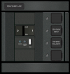
I've been looking for the best way to implement a new shore power connection w/ELCI, and Peter @ PKYS pointed me to a nice solution today. Its a Blue Sea custom panel that is panel mountable. I love that solution, but still have question as to suitability for my mounting location. PM me if you want more info.
As far as a breaker and should you go ELCI, it's just not that much money to do it right up front. I'm going to add it for resale/survey proofing.
Hopefully we haven't completely hijacked your thread without providing some useful info
I've been looking for the best way to implement a new shore power connection w/ELCI, and Peter @ PKYS pointed me to a nice solution today. Its a Blue Sea custom panel that is panel mountable. I love that solution, but still have question as to suitability for my mounting location. PM me if you want more info.
As far as a breaker and should you go ELCI, it's just not that much money to do it right up front. I'm going to add it for resale/survey proofing.