Helm switch label lighting not working

Dave M.

New Member
TECHNICAL Contributor
Oct 9, 2006
874
Hermiston, OR
Boat Info
270 DA
Engines
7.4L, Bravo II
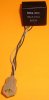
The labels on the switches at the helm do not light up when I turn on the Nav lights. The instruments do light properly. The lights and a small encapsulated box that feed them are made by El Tech. I have not been able to find any information about these parts. I suspect the encapsulated box is a voltage converter that drives the lights, or luminescent strips, or whatever they are. But I don't know what the output voltage of this little box should be, or whether it is AC or DC.

Does anyone have any experience with replacing this, and what it really does? On the part is:
El Tech BLI060/ISW5165

Any info appreciated!

This thread belongs in the electrical section.
 
My dash has an obscure dimmer knob. Make sure you haven't accidently dimmed the lights. I thought mine were out for a while until I was cleaning the panel one day and had to smack my head.
DOH!
 
370Dancer said:
My dash has an obscure dimmer knob. Make sure you haven't accidently dimmed the lights. I thought mine were out for a while until I was cleaning the panel one day and had to smack my head.
DOH!

Yes, I have know about the knob,and it works fine. My instrument lights work, just the backlighting for the switches does not work. I have been doing a bit of looking on the internet. I think they are flat electroluminescent panels. And if so, then they need driven at about 100 V AC, maybe a bit more, at 400 Hz. The driver to make this voltage from 12V DC is the little black encapsulated cube behind the panel, if my theory is right.

From what I read, the displays don't have a long life, half life is maybe a thousand hours. They are also prone to moisture damage. But I suspect my problem is the DC to AC converter. I have an oscilloscope, so I will check it out to see if it has any output. But I am not 100% positive this is what the parts really are and do.

But if I find the converter has no output, it should be possible to check the luminescent panels by applying 120 VAC, 60 Hz, and they should light up some. If they are not what I think they are, then I suspect putting AC on them like that would force out all the smoke. Most electronics things don't work any more when you let the smoke out.
 
MLauman said:
Be sure to have a camera ready for the smoke! :thumbsup:

Good idea! If I get my timing just right, I can catch it is the plastic encapsulation splits open the the smoke breaks free. :grin:
 
I have checked the voltage applies to the backlighting panels. I find there is no DC or AC voltage.

If the panels really are electroluminescent as I think, then they should be driven with up to 130 V AC, at around 400 Hz. An EL panel load is not resistive, it is capacitive, and rather low capacitance. So there is not much current needed to drive them.

The wires going to my backlighting panels are quite small, so small that I really questioned whether they could be rated for 120 V AC or not. So I took my magnifying glass out to try and read the writing on the wire. I found the wire has the following characteristics:

AWG 22, 22 gauge wire
Marked '300V'
Rated for 80 degrees C
Marked '1007', and CSA AWM T1

I looked it up, and found the wire is UL 1007 spec, and CSA AWM T1 is an equivalent Canadian spec. The 1007 UL spec does state the wire is rated for 300 V, 80 degrees C, and may be any size from AWG 16 to AWG 32.

http://www.conwire.com/Hook-upwire.htm
http://www.thermalmemory.freeserve.co.uk/UL1061.pdf

So this is obviously consistent with the device being driven with 120 V AC.
 
The panel lighting module should be driven by 12vdc. If you don't have any voltage to the module with the nav lights turned on, and the dimmer all the way up, then I suspect you have found your issue.

I took a quick glance through your 1996 parts manual, and didn't see where the illumination portion of the dash panel is called out separately.

http://owners.searay.com/parts_manuals.asp?tab=&year=1996
 
Thanks for taking a look at the parts manual. I did not find anything there either, but have not looked at it in the last week. So I could have overlooked something.

I have posted the electrical diagram for the helm switch panel for my boat here. If you scroll halfway down the page until you find the three pictures side by side (switches, instrument, breakers), and click on the switch panel, it will bring up the electrical diagram in a new window. Then if you enlarge that in your browser by doing whatever it is you do in Windows, you will see the wiring to the module driver box.

I have checked the voltage at the last wire splice before going into the box, and the voltage is good that far. The next step before doing anything radical is to take needles and puncture throught the insulation and into the wire right at the input to the module and check for 12 V, just in case a wire feeding it is broken internally.

And it that it good, then it is time to look for a replacent light driver, or design one, or change over to LED backlighting.
 
I was taking a nice mid-afternoon nap :smt015 when a design for the electroluminescent driver just sort of popped into my head. A few details remained to be worked out, but it should work well enough to check and see that, when driven with a higher frequency AC voltage, the lighting will work. I suppose that is normal, because if you just think about the requirements of a problem, then let your subconscious work on it, it will be at work while you are doing other things. Like napping. So the two issues that I could see were:
:smt017 How do I generate a nice square wave that is faster than 60 Hz, and
:huh: How do I boost it up to over 100 V?

I was just sort of waking up when I realized the easy way to get a nice square wave. Any good IT guy with more than just a few years under his belt will have fond memories when you say those words we all seemed to use -- “Send me some RY'sâ€. The guy at the other end would sit down at his teletype and hit the R and Y keys in succession, as fast as the rotating machinery would take them. :smt024 Since the baudot code for R is 01010 and Y is 10101, this puts out a nice square wave on the 20 mA current loop. With this nice square wave, you could adjust your receive side adjustments to center them up. Since these things aren't used much anymore, I figure I should be able to pick one up that runs on AC and does 300 baud (to get the frequency up) on E-Bay pretty cheap. Since I have inverter power on the boat, I can just plug it in.

I knew when I woke I would need a resistor to turn the current into voltage, but didn't know what size. Would figure that out later, but I knew it would need to not be too high a voltage. What I DID know when I awoke though, was how I was going to get the voltage boosted up to over 100 Volts. My wife has been complaining for years about those old 6.3 volt filament transformers in the basement that I refuse to throw away. But they are unused, and still wrapped in some nice soft packing material. Now I had a need for one. This would show her I was right all these years! I will just hook up the TTY output, from across some resistor I did not know the value of yet, to the low voltage filament side. Then I would take the side that normally would hook to 120 V AC, and connect it to the electroluminescent panel. Send some RY's, and Voilà! Light! :smt038

So having this flash of insight that seemed to solve most of the issues, it was just a matter of figuring out what resistor to use. I struggled to get "ELI the ICE man" out of my mind, as I knew that was the wrong formula. Being an engineer, I soon remembered that resistors turn current into voltage. I wanted to choose a spiffy resistor for this application. I thought of the prestigious Nikon cameras with their red racing stripe, and thought rather than just one, a nice group of three would be better. So I did some searching on the internet for resistors with three red racing stripes, and found they are commonly available, and would have a resistance of 2.2 kohms.

I recalled tthat one should multiply the current times the resistance to determine the voltage. I came up with .02 times 2200, so I put that in a spreadsheet to work it out. It came out to be 44 volts. Then run that into the 6.3 V side of the transformer, and see what comes out 120 V side. So I put those numbers in the spreadsheet too. 838.1 volts peak to peak. OUCH! :smt009

That's not gonna work. Determined not to give up on the three red racing stripes, I thought to put three of these in parallel to get the resistance, thus the voltage, down. So I stuck in 2200/3, and out came 279.37 volts, peak to peak. But AC is measured from ground to the plus or minus voltage, so divide that by two. It came out 139.68, call it 140 volts. Can't hardly get any better than that. :thumbsup:

I got the frequency up, got a nice voltage, can turn it on and off at will, and the parts should be quite cheap. Only drawback is size, but we are talking a 27 foot boat here, so how much of a problem can that be? :grin:

Just a few more preliminary checks to make sure I don't have something obvious wrong with my current setup, and maybe I will give this a try. Not sure if I should try and get a patent on it or not. But that has to wait until I get to feeling a little more stable on my feet. Those darned narcotics the Dr put me on after my minor 'repair job' still have me feeling a bit wobbly. And he warned to take it easy on them before bedtime, as it can cause some odd and unpleasant dreams. I did not experience that. :cool:
 
I think I got all that except the part between the nap and the narcotics! :huh:
Glad you worked it out - you DID, didn't you?
 
I have the same issue what I have been able to find out may provid e the missing link..My boat is a 87 Sea Ray Pachanga 22 it does not have a dimmer for the backlights as some 88 and later models seem to have BUT I do have the power inverter little black box with a 4 wire connector one gray one black one white and one black/white stripe the lettering on its is ERG INC E612-E131 then 8633A the last group is the mfg date 86-year 1986 33=33rds week and A= day of the week =Monday. the manufacturer can be found here: http://www.ergpower.com/ however the technical support guy was not too friendly I asked him if there was anyway to test the unit and he replied kinda rudely NO.. So I asked if i sent him mine could he test it and determine if it was for sure failed or not and again he was kind of rude about it. However he WAS willing to sell me a replacement for about $125.00 if I remember correctly. Which I wouldn't mind so much as long as I knew for sure that was the problem. I just don't want to replace the inverter and find out that the problem is really the light strips as they are not too easy to find either. Hope this helps if worse comes to worse i am trying to figure out and alternative possibly a small piece of pvc cut in half with a couple of white or maybe blue led's and secure it to the backside of the dash. If you hold a flashlight behind the dash when its dark you can see it doesn't take much light to make the entire strips glow. Hope this helps.
 

Attachments

  • erg2_205.jpg
    erg2_205.jpg
    28.1 KB · Views: 550
Interesting! I know how to test it, that is what I used to do for a living. I will see what I can come up with tomorrow, if possible. I am in the middle to a spring time upgrade of the irrigation system on my 7 acres of pasture. Been working on it for a week or two, my boat misses me. :smt089

What I can tell you off the top of my head is that most present day units would put out AC, roughly on the order of 90 to 130 volts. The frequency might be anywhere between 250 and 450 Hz. I don't know about the waveshape. It might be sinusoid, but would be cheaper to make a triangle wave, or even cheaper to make a square wave. But I think a square wave is not desired, as the edges are too steep. They also have a lot of harmonics, by definition.

With a good DMM, you can measure and see if you are getting AC, and if so what voltage. A good DMM should also be able to count frequency in this range.

$125 is quite a high price to pay. I think the parts for one might cost $5. I have thought about making my own, and have done a bit of searching for a good design, or design start. But I feel that this is old technology, and if possible, one should switch to LED lighting. I have not looked at the back side of the panel to see if this might be possible. I don't know what the physical constraints are.
 
OK so a lil more info...SO I had a lil time today to try and mess with it what I did find was that I am getting 12V to the inverter. The two grey wires are the power IN to the inverter one goes to the Nav Lights switch the other goes to the anchor light switch It would only get power from the Nav Light switch though ..So that helsp clear up some of the mystery. The black and the white wires I traced to the back light strips on the back of the dash. Found what I think is a part number on the light strips 1761 83003 is what was printed SOOOO I will give sea ray a call tommorrow and see if thats a good P/N But Since I have 12V going in to the inverter and NOTHING coming out I guess its fair to assume that the inverter has died??
 
Assuming that you measured the output with your meter on AC, and you made good contact with the conductors, then I think yes, your inverter is fried. The manufacturer will have made it difficult for you to get to the AC side, as it is over 100V AC. Not much current capability though, the inverter drives a very small load, so does not need to put out much power.

I sent off an e-mail query to a parts manufacturer last night, but have not heard back. They probably don't want to talk about anything less than 10,000 parts.
 

Forum statistics

Threads
113,155
Messages
1,427,402
Members
61,061
Latest member
Rod01
Back
Top