Actisense EMU-1 Engine converter analog to Digital

Skybolt

Well-Known Member
Nov 11, 2014
6,422
Kent Narrows, MD
Boat Info
Reel Nauti
460 EC
Engines
Detroit 6v92TA
(Low profile's)
Alison Gears
Westerbeke
12.5kw Genset
Some of you may have followed my post over at THT about converting my Detroit's over to digital and NMEA 2000. I had gone through every option out there, except the actisense EMU-1 because they did not support custom calibrating. They still don’t but they do support custom sender curves. The difference is with the custom sender curve you can get the sender characteristics (resistance curve) from the manufacturer and enter it in the Actisense software now. That’s not the same as mapping the display to a sender value which in some cases is a whole lot easier because the resistance curve doesn’t always match what the sender actually is reading.

I was using the Checto G2 and for a few years it worked great until I had an alternator go and it took out the G2. I tried fixing it and thought I had but in trying to calibrate it again with new software proved to be a venture in futility. So I was left with buying a new G2 and dealing with programming issues (more detail starting at post 73 in the above thread) or trying something else again. Neither option was appealing to me, but I decided to try the EMU-1 and see if I could make life a little easier.

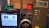
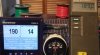
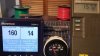
So far I received the Actisense EMU-1 and the USB to NMEA 2000 Acitsense converter required to program the EMU-1 and started testing it. I decided to mock up everything before I rip the boat apart again. I have spare senders for the engines and grabbed them and took my DSM410 N2K Display back home to mock up a small N2K network and test the EMU. I hooked up a VDO Vision Black 100-250 temp gauge and sender (VDO 323-419), along with the EMU hooked in parallel and started to test the readings. I am using a Fluke 51 temp meter and coffee cup with a cup boiler to heat the water. The sender is suspended in the water with wire. So this mocks my setup in the boat for the most part. I put in new temp gauges when I first started this project a few years ago. But the gauges are off to the side in a lower switch panel basically out of sight and only there to verify things when there is a problem. I have 6v92’s and they are wet liners which are toast at temps above 195-200 degrees and run at 180 in 80-90 degree water. So not much margin to catch any issue.

So back to the testing, in short, the EMU tracked the temp from 100 to 212 within 3 degrees F. and from 212 to room temp it was within 1-2 degrees. I did this a few times and it was very stable and repeatable so that’s a great start. I think the temperature heating was too quick for the sender to track properly.

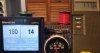
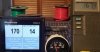
I tested the pressure with a Fluke multi-meter and pressure adapter (Fluke pv350). I used my spare VDO 0-80PSI sender. I rigged a setup with my air compressor in the garage and ran it through 0-90 PSI up and down a few times in intervals of 5 PSI. The EMU was accurate within 2 PSI, absolutely amazing! It did top off at 70 PSI but I think that is the limit of the sender. My adapter goes to 350 PSI.

The other nice thing about the EMU is that it has alarm inputs and they post to the 127489 engine dynamic PGN. That means they can be read by any MFD, even the older ones that don’t have configurable engine screens but also have the “idiot light” icons in them, like my older Garmin 4212. The G2 did not support the alarms though an input, and only through software programmed alarms. Not that same as the sender switches that are analog triggers. I trust that a whole lot more because it is coming from an additional sender that has been used and tested for years.

The EMU has some short cummings though, it doesn’t have enough inputs to support two engines properly. The first one is they only support one battery, you can assign it to either the 127489 engine PGN or the 127508 battery PGN and you can assign the instance. But to support two batteries you need a second EMU, and that is stated in there manual. The other thing is it only has four alarm inputs. You can get by with using only water and oil alarms. So you could get by with only one EMU for two engines if needed as it does have two tach inputs. But with two EMU-1’s you get six inputs for engine data and four for alarms. More then enough for one engine. It does support the transmission PNG’s as well.

So far I am liking the Actisense EMU-1 very much. This coming weekend I am going to install one EMU and if all goes well then a second one. But I plan on testing it out on a trip before I get the second one. Programming the EMU-1 was a breeze and all of the stock profiles worked right out of the box with no need to enter custom curves. Pretty funning because that was my reason for not trying the EMU-1 in the first place, if I had tried it out I would have saved myself a ton of aggravation and money. Although the G2 worked great for a few years and would still be using it if not for the alternator frying it.
 
Last edited:
So back to the testing, in short, the EMU tracked the temp from 100 to 212 within 3 degrees F. and from 212 to room temp it was within 1-2 degrees. I did this a few times and it was very stable and repeatable so that’s a great start. I think the temperature heating was too quick for the sender to track properly.
It has preprogramed thermistor curves? Or is there a way to plot in the curve?
I was working with the Noland converters years ago and had to settle with a linearized conversion on a reasonable part of the curve (pic) - This is from the same type of testing as you did. There are a set of equations called Steinhart and Hart which will accurately output a temperature based upon resistance for thermistors which I had tried to get Noland to integrate but that went nowhere.
ThermistorLinearization.jpg
 
Last edited:
It has preprogramed thermistor curves? Or is there a way to plot in the curve?

They recently came out with a "Custom Gauge Manager" that allows for custom sender curves to be entered. The attached is an example of one I entered. These are saved to disk and can be transported and loaded on other systems. There are also stock curves that work quite well. This was created by using the VDO resistance curve they publish. I entered it is degrees C then changed the drop down to degrees F and saved the file. It's a little strange that they call the input side volts, but it is clearly resistance.

upload_2020-10-20_8-15-31.png


I was working with the Noland converters years ago and had to settle with a linearized conversion on a reasonable part of the curve (pic) - This is from the same type of testing as you did. There are a set of equations called Steinhart and Hart which will accurately output a temperature based upon resistance for thermistors which I had tried to get Noland to integrate but that went nowhere. ...

That is funny, I also was working with them, I believe in 2016 for the same reason and was promised the same thing. I also tried to get the tach input working and sent him an Aetna signal generator and nothing came of that except the returned sender.

As mentioned above, so far this is right on the mark with both temperature and pressure. All that remains to be seen is how it handles the tach signals. Nolands tach curve was not linear and could not track the upper end. My hopes are that this device will perform as well as the rest of it has.
 
Last edited:
Here are the test pic's of the temperature sender VDO # 323-419
 

Attachments

  • 20201020_153240.jpg
    20201020_153240.jpg
    121.6 KB · Views: 418
  • 20201020_153523.jpg
    20201020_153523.jpg
    109 KB · Views: 386
  • 20201020_153727.jpg
    20201020_153727.jpg
    102.9 KB · Views: 375
  • 20201020_153959.jpg
    20201020_153959.jpg
    123.3 KB · Views: 386
  • 20201020_154327.jpg
    20201020_154327.jpg
    123.6 KB · Views: 379
Went down to the boat tonight to install the EMU-1 with laptop in hand expecting to have to calibrate something. To my surprise with everything wired up and started the engines up the tachs worked right out of the gate. I had set the software to 4 pulses since I have Aetna Engineering senders that output 8 pulses per rev., but my Detroits have 2:1 gearing off of the blower cam. So thats 4 pulses per rev. The EMU-1 has precision to the 1/100 or 0.00 and all I set was 4.00 for both and they ran perfectly through 1800 rpm. I was expecting to have to change to something like 4.1 or 4.08 like I have had to do in the past.

So the real test will be this weekend and I take her out for a 3 hour tour ...
 
Last edited:
Good news!! Glad its working!

So far I have been able to get good results from my Chetco G2, but dred the day I have to replace. I was able to get everything working pretty well, and with the addition of a couple or Maretron parts, I have been able to get a good instrument package.

My N2K tachs are usually +/-10 rpm of what I have on the Aetna's. This I believe is due to the way the Chetco counts pulses...its not a 1-1 ratio, but base on a multiplier... its close enough to use every day.

I added Maretron TLM100 fuel level sensors, and repurposed the analog fuel channels on the G2 to measure Boost pressure.

I added a Maretron TMP100 with 2 of their EGT probes to add EGT.

The remaining channels on the Chetco G2 give Battery/Alternator Voltage, Coolant Temp, Oil Pressure, Transmission Pressure and Transmission Temp.

I'm not sure I could replicate this set up with the EMU, although I might add one to the generator to keep track of that engine, and add Maretron to keep track of the Electrical side.

My nagging issues are that I cant get the G2 to output the correct transmission temp on the N2K network. G2 unit is reading the temp correctly, but something odd converting it to the N2K side. Orlando and I have discussed this and he may have a solution. Oil pressure is off because I haven't been able to replace the oil pressure senders to match the pre defined curve. I'll get to it this winter.
 
Last edited:
Good news!! Glad its working!
... I'm not sure I could replicate this set up with the EMU ...

Thanks, if all goes well on Saturday I am ordering another one so all of the engine alarms and data can be tracked. Two EMU-1's equals the inputs that are available on the G2, minus the four relays, also adds an addition pulse input. They also track the transmission PGN's as well.

My N2K tachs are usually +/-10 rpm of what I have on the Aetna's. This I believe is due to the way the Chetco counts pulses...its not a 1-1 ratio, but base on a multiplier... its close enough to use every day.

You might want to try increasing the resolution of Chetco's math for counting the pulses. Increase the scale to divide by 10 instead of 1. then you have hundredths resolution instead of tenth's, or two digit opposed to one. So the divided scale is 15.1 in this case as demonstrated by the SS below.

upload_2020-10-23_8-16-58.png


The G2 is a nice piece of equipment, but vDash is a piece of something else, and the only reason I switched to the EMU-1 instead of replacing my burnt out G2. By using two EMU-1's I gain another engine input because they use the supply voltage to output the battery PGN which leaves the six analog inputs for engine data. Also by using two EMU-1's I can get all of the engine data including adding the transmission parameters, but I can also add the generator to the remaining channels of each EMU-1 for the generator engine data.

With regards to the generator data, if you have AC monitoring, you can use the hertz to know your RPM. That way you don't have to add an RPM pickup. At 60hz your generator is rotating @1800 rpm or 600 rpm/20 hz. that math allows to adjust the RPM, although adjusting to hertz is more important.

The only thing I want to add but unsure it is measurable, is boost pressure. The only place I could a sensor is in the the turbo accumulator that feeds the blower. I am not sure that is the right place to add a pressure sensor. I might try a mechanical vacuum gauge first to see if there is measurable pressure there. It would be nice to know right away if I loose a turbo.
 
Last edited:
Thanks for the idea on the Chetco match...its a fuzzy logic black box most of the time. I'll have to look at my chetco unit set up this winter, and see if I can't get the last few channels dialed in, including the above tach math...

I was thinking about adding AC and DC electrical monitoring, but pretty expensive. Really all I would like to see on the network is the generator temperature, and the DC SoC for the house battery. However, an EMU (or similar device) would be required for the generator, so might as well get the RPM reading while I'm at it. DC SoC for one battery is pretty cheap and easy.

Boost was an easy add for me on the CAT's as there are 3 ports on each engine, and only a inexpensive fitting is required to install a basic pressure transducer (0-30 psi in the case of the 3126). The electrical side is easy. Not sure on your DD's, but anywhere upstream of the turbo should work. I assume you might have to drill and tap a hole?
 
The AC monitor is worth the investment IMO. The DC not so much, IMO. For one it allows you to monitor the generator. My generator runs for 2-3 days sometimes and I have a screen on the DSM410 for monitoring the genset, oil, temp, AC voltage and Hertz. For the SoC, I have a newer Promariner with remote panel and that does a really good job of cycling the batteries and SoC progress on the display in percentage.

For me the boost is the tough one. I would have to remove the accumulator top horn and tap. That in and of itself isn't bad 6 bolts and a gasket. It's the oil gallery and governor housing that has to be removed that makes me nervous, but will most likely go that route this winter.
 
Last edited:
I was able to get out yesterday and give the EMU-1 a run. Everything worked pretty well, not quite as well a on the bench, but what ever does. The engine temps seem to be with in +5 degrees of the mechanical gauge.
The oil pressure was almost 5-8 PSI lower on the high end, reading 58 or so with the mechanical gauge on the engine read 65PSI. Then went the opposite on the low end was reading ~8 when it was 15PSI.

I can probably live with those differences for the most part. But the tach's were as I feared, they were bouncing around and not reading correctly at all. I am sharing the signal with the Aetna Engineering tach's so I think the is my problem. The Aetna Tach were solid, but the N2K would read above and below the actual by more then 50rpm and totally drop out at times. My senders are dual station senders, so I am going to run cat6 wire from them and see how that goes. The calibration multiplier/divider looks like it will be fine if I can get the signal stable.

The other issue is that EMU-1 activates the engine alarms as soon as power is applied, meaning low oil pressure alarms happen instantly. So not sure what I am going to do with that one. Maybe a power on delay relay for the alarm relays I am using. Have to give it some more thought.

EDIT: Corrected above paragraph.
 
Last edited:
I was able to get out yesterday and give the EMU-1 a run. Everything worked pretty well, not quite as well a on the bench, but what ever does. The engine temps seem to be with in +5 degrees of the mechanical gauge.
The oil pressure was almost 5-8 PSI lower on the high end, reading 58 or so with the mechanical gauge on the engine read 65PSI. Then went the opposite on the low end was reading ~8 when it was 15PSI.

I can probably live with those differences for the most part. But the tach's were as I feared, they were bouncing around and not reading correctly at all. I am sharing the signal with the Aetna Engineering tach's so I think the is my problem. They would read above and below the actual by more then 50rpm and totally drop out at times. My senders are dual station senders, so I am going to run cat6 wire from them and see how that goes. The calibration multiplier/divider looks like it will be fine if I can get the signal stable.

The other issue is that it activates the engine alarms as soon as power is applied, so not sure what I am going to do with that one. Maybe a power on delay relay for the alarm relays I am using. Have to give it some more thought.
The problem with the tach signal is the hall effect sensor (the RPM pulse generator) may be getting regulated power from more than one source. However, I was unaware that those older engines monitored RPM and provided such alarms. Well, now that I think about it the old Detroits could have run-away conditions that may be alarmed.....
 
Sorry, I didn't explain myself well enough it seems. The alarms that activate too soon are the low oil pressure. They happen as soon as power is applied and the EMU-1 boots. The tach signals are not monitored at all by the non-DDEC engines. I would never own a DDEC engine. But you are correct they can run away when they get older and tired. Mine still have the black cross-hatch in the liners. Thats not to say a cracked ring couldn't cause that though. Fingers crossed that doesn't happen.

I am not sure the Aetna Engineering 8902 sender is hall effect. These senders will generate a signal if turned by a drill motor or such. They are basically an AC generator.

https://www.aetnaengineering.com/wp-content/uploads/2016/01/8902-Spec-Sheet.pdf

The Noland RS11 had this type of problem as well. After I finally had it stabilized it wouldn't track the RPM range correctly and was constantly 50-75 RPM off. I am hopping that isn't the case with the EMU-1.
 
Last edited:
Looks like you have a good start on the project. All of the instrument errors seem to be with in operating range, and as long as they read consistent, it should be OK. Tach are always a pain, as I mentioned, mine are +/-10 and good enough, but I may try your remedy playing with the multiplier.

As far as the low oil pressure alarm at start up, that is how the CAT engines operate...sound until I have pressure, so I think that is how they are supposed to operate.
 
... As far as the low oil pressure alarm at start up, that is how the CAT engines operate...sound until I have pressure, so I think that is how they are supposed to operate.

It would be nice if the EMU-1 would silence it's own alarms if the condition was corrected, then it wouldn't matter so much. The Garmin GMI20's alarm and have to be acknowledged, not to mention the MFD's as well.

Perhaps there are settings I haven't explored yet. I haven't tried to see if there are settings on the displays for alarm conditions etc. Or I am using a relay board to trigger the alarms so I am thinking a power delay relay set to ~2-3 minutes after turning the breakers/ignition switches on to delay the power on of that board.

Thats a problem...the standard SR low oil pressure alarm silences automatically once pressure is measured above the threshold. The locking relay of the alarm needs to be changed to just an on/off type. I assume the alarm relay is in the EMU?
 
The alarm "relay" is a PCB I added for the G2 originally, my G2 was configured to activate on +12v not a low like the senders do. So I added a relay board to invert the states. The outputs of the relay board go to the EMU-1 and then that sends the alarm. The EMU-1 has a configurable threshold for the alarm inputs and I was going to get rid of that relay board. But now I may have to add another to the mix, not what I want to do.

Going over to the boat later to test and check the alarms and the MFD options as well.

EDIT: Yes the SR monitor operates correctly and I believe the EMU-1 does as well. The displays hold on to the alarm once it has been activated and need to be acknowledged manually. Thats where the issue is and the way that Garmin handles this.
 
So it looks like I was too impatient and had to silence the alarm before I started the engines. Because the alarms do silence after the engines are started. But do not silence when shut down even when the EMU-1 is turned off. The MFD's hold on too the alarms until acknowledged.

I have three versions of displays, GMI20(2), 4212(2) and a 7608. If I acknowledge the alarm on a 4212 or a GMI20 then the alarm silences on those displays. Meaning they will all silence but the 7608 does not (yes the 7608 is connected to the Garmin Marine Network). I guess I could turn the alarms off (system setting to not respond to those alarms) for the 7608 and only leave them on the older Garmin units that talk to each other when the alarms are acknowledged on a different display. But what a PITA to have to ack every alarm when shutting down everytime ...

I guess I need to start over with the relay board I have. Hook the engine alarm wires directly to the EMU-1 and see what happens then perhaps a different kind of relay setup can fix this. Didn't see these issues on the way into this setup. Still very glad the alarms are what they are and now alarming everywhere. Saves on a seperate alarm output.
 
I think I figured out how to fix this issue. I currently have an 8 input relay board for my engine alarms that I used for the Chetco G2 and like the concept of that board. So if I use two 4 channel boards I can power them with the start/stop switch's. The EMU-1's will be connected to the breakers that supply the switches which get turned on first but can also be left one at times for diagnostic purposes. If the alarm PCB is powered off of the start/stop switch then the alarms will not happen unless the engine is running.

I am still only working with one EMU-1, I am still having issues with the tach readings. I have my port engine working perfectly, so one would think the starboard engine would follow in line, but not the case. For some reason the STB is jumping around 100-150 RPM's lower at cruise then the port, even though the Aetna Engineering tachs are dead on with the sync active. I am going to replace the sender first with a spare I have. Then try running CAT6 for the tachs. Then try a rectifier of sorts if need be.

I had this exact same problem when trying to use a NoLand RS11 and was never able to get the tach right, the best I could do was a 50 RPM difference. That's too much for my 2 cycle Detroits. Hopefully this is a lot different then what I experienced with the RS11, since the port engine is working ok right now. To check the EMU-1 out, I am going to swap the inputs first and see what changes and proceed from there.

I have been in touch with their tech support via email and described this issue to them and received this response:

"The new firmware being released soon is designed to fix Tacho issues we have seen with 1.015 firmware. In regards to the Tach readings from the EMU-1, are they reasonably close to the actual RPM? Of course apart from the strange 150RPM difference between the two at the moment."

A little discerning don't you think?
 
Last edited:
Possibly look into a low pressure switch (10 PSIG) and install in the engine oil system. Use that to turn on the channels that are alarming via relays only when oil pressure is above say 10 PSIG (engine has started and running).
 

Forum statistics

Threads
113,117
Messages
1,426,410
Members
61,029
Latest member
Curious
Back
Top