KevinC
Well-Known Member
When I purchased my boat this was on my wish list but I figured I could always add one.
This thread is here to document my installation so that others may find similar inspiration.
Project Inventory:
Just some notes regarding my work:
Now this project took a lot of planning and based on last year costs I was able to shop around and complete this for less than $950. The only compromise I think I made was that I did not install a battery solenoid that would have come from the factory. This was mitigated buy using the switched thermal breaker.
Timing wise I would budget a week of part time work daily unless you can work this start to finish.
That will also give you time to work things out that your may encounter. I always find it better to not rush and actually enjoy the project.
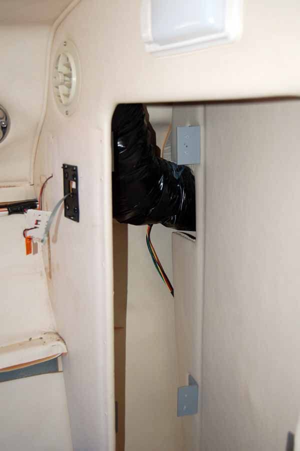
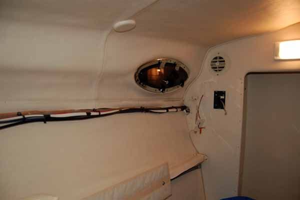
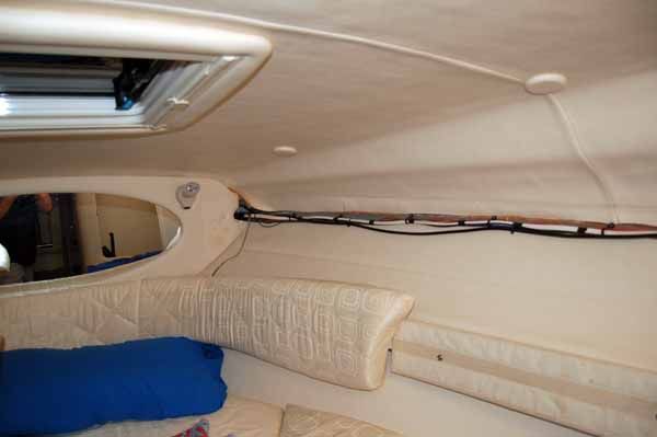
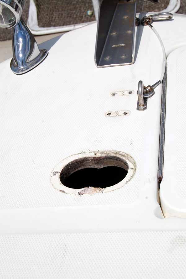
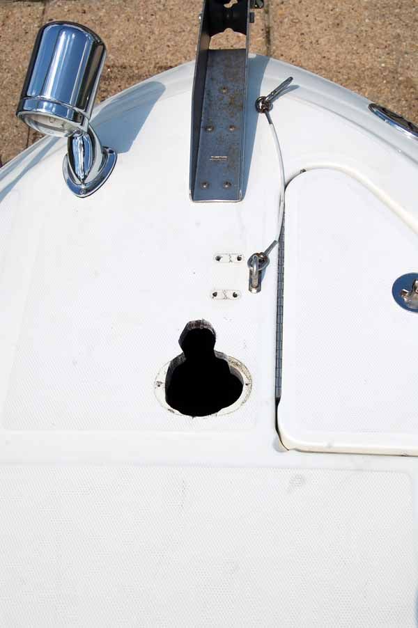
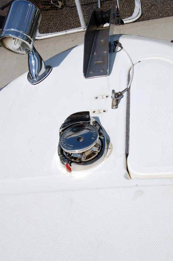
I am going to post a bunch of photos along with descriptions.
I pre-wired this install for foot switches at the bow that will not be shown yet as I will be completing them this spring. Take my word, even if you don't think you will need them, you will want to wire for them as you will not want to disassemble the cabin again to run couple of small wires.
I hope you find this interesting. I loved he project and have received many complements. This project diary is my payback for all the great information I have received. If you want a windlass, have the time, enjoy working with tools and want to save a lot of money this is a great project an my notes should help.
Of course, this was done on a 2003 260 Sundancer and your model may vary slightly however the process will be similar.
This thread is here to document my installation so that others may find similar inspiration.
Project Inventory:
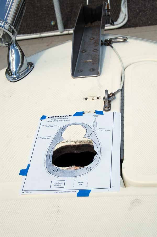
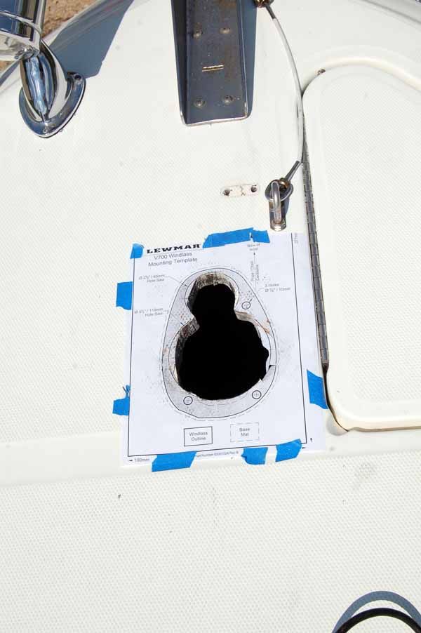
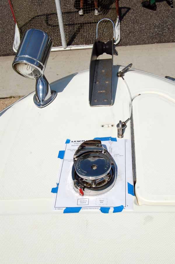
- LEWMAR V700G VERTICAL WINDLASS (WINDLASS, ROCKER, BREAKER AND CONTACTOR/SOLENOID)
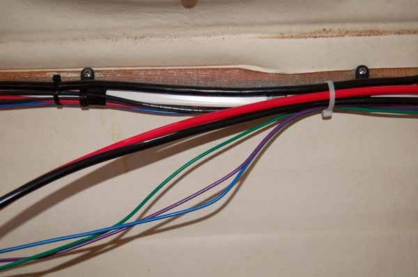
- 6 AWG TINNED MARINE BATTERY CABLE (APPROX 50FT RED & 50FT BLACK)
- 16 AWG TINNED MARINE PRIMARY WIRE (APPROX 25FT EACH GREEN, BLUE & PURPLE)
- BUSSMAN 187 SERIES 35A (I WANTED A FLUSH MOUNT)
- 6 AWG TINNED SEAMLESS MARINE LUGS 1/4 POST (APPROX 25)
- SOME DUAL-WALL ADHESIVE HEAT SHRINK 1/2" RED (3:1 RATIO)
- VARIOUS SIZES OF OTHER MARINE GRADE SHRINK TUBING
- VARIOUS OTHER TYPICAL MARINE
Just some notes regarding my work:
- For all my connections were crimped and sealed with marine grade shrink tubing to seal them.
- All the 6AWG terminals were tinned seamless connector with for a 1/4" post.
- The 6AWG cable is thick so I would up purchasing a hydraulic crimper from harbor freight that made great crimps.
- I think there were two that I had to drill to slightly enlarge.
- My terminal connections to posts were booted.
- I used slightly less than 1 million zip ties.
- Very little of this work required more than one person.
Now this project took a lot of planning and based on last year costs I was able to shop around and complete this for less than $950. The only compromise I think I made was that I did not install a battery solenoid that would have come from the factory. This was mitigated buy using the switched thermal breaker.
Timing wise I would budget a week of part time work daily unless you can work this start to finish.
That will also give you time to work things out that your may encounter. I always find it better to not rush and actually enjoy the project.
I am going to post a bunch of photos along with descriptions.
I pre-wired this install for foot switches at the bow that will not be shown yet as I will be completing them this spring. Take my word, even if you don't think you will need them, you will want to wire for them as you will not want to disassemble the cabin again to run couple of small wires.
I hope you find this interesting. I loved he project and have received many complements. This project diary is my payback for all the great information I have received. If you want a windlass, have the time, enjoy working with tools and want to save a lot of money this is a great project an my notes should help.
Of course, this was done on a 2003 260 Sundancer and your model may vary slightly however the process will be similar.